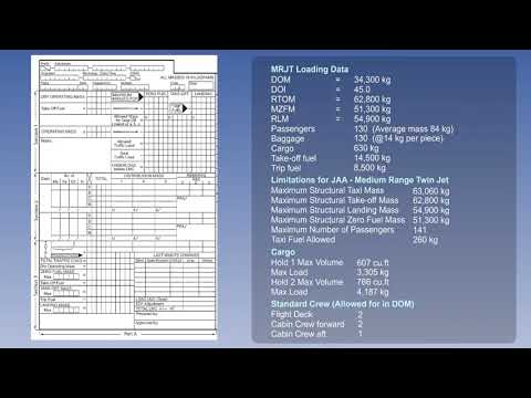
Load Sheet For Piston Engine | Lecture 07
Introduction to Mass and Balance Regulations
Overview of Practical Applications
- The session transitions from theoretical concepts of mass and balance regulations to practical applications, focusing on solving problems related to the center of gravity (CG) of an airplane.
- Reference is made to CAP 696 Single Engine Piston as the foundational document for calculations regarding mass and balance.
Loading Manifest Preparation
- Participants will complete a loading manifest using fictitious data, entering values into the mass column corresponding to items listed in Figure 2.4.
- The total mass for items 1 through 7 must be calculated as part of this exercise.
Calculating Zero Fuel Mass
- The zero fuel mass is determined to be 3295 pounds, with the arm for basic empty mass noted at 77.7 inches from Section 2 Page 1 of CAP.
- Moments are calculated by multiplying each mass by its arm, dividing by a constant (100), and recording results in the moment column.
Fuel Conversion and Totaling Mass
- A method for converting fuel volume to mass is referenced from previous lessons; specific paragraphs in CAP provide conversion data.
- After calculating ramp fuel moments, participants sum both the mass and moment columns to obtain subtotal ramp figures before proceeding with takeoff calculations.
Finalizing Load Sheet Table
- The takeoff mass is computed after accounting for fixed amounts used during start, taxi, and run-up phases.
- Subtotal landing masses are derived by subtracting trip fuel masses from takeoff figures, completing the load sheet table.
Center of Gravity Envelope Analysis
Plotting Takeoff Data
- To find the takeoff CG, a horizontal line representing takeoff mass (3642 pounds) is drawn alongside a diagonal line indicating moment (3102).
- The intersection point determines that the CG for takeoff is at 85.2 inches after datum; this value falls within acceptable limits indicated on Figure 2.5.
Landing Data Representation
- For landing analysis, similar plotting occurs with a horizontal line at landing weight (3402 pounds), followed by a diagonal line showing moment (2922).
- This results in a CG position of 85.9 inches after datum which also remains within limits according to graphical representation guidelines.
Conclusion on Center of Gravity Calculations
Verification Against Limits
- It’s emphasized that while CG can be calculated via total moment divided by total mass, these values must still align with regulatory limits.
- Utilizing graphical methods provides immediate visual confirmation that calculated values remain within operational limits.
Turn any video into a summary like this
YouTube links, meetings, lectures. With transcripts, search, and chat.