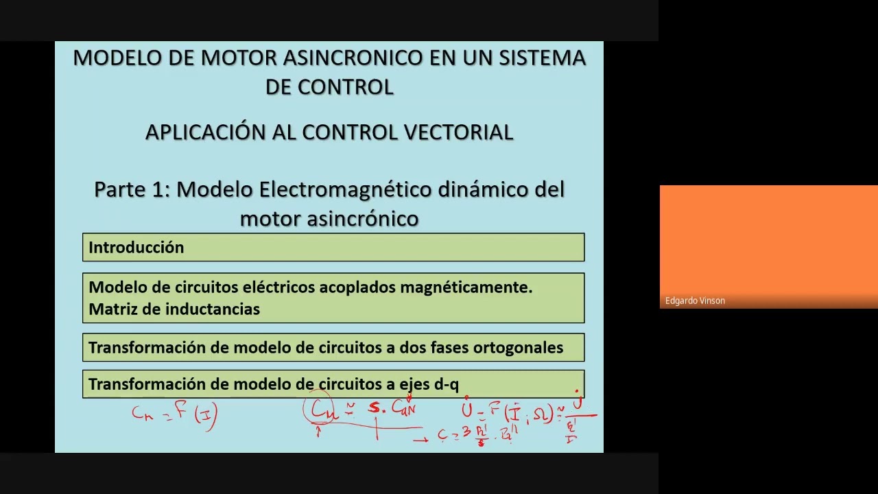
AyCE 2021 06 10
New Section
The speaker introduces the topic of synchronous machine modeling and its importance in understanding and simulating machine behavior under varying conditions.
Introduction to Synchronous Machine Modeling
- Synchronous machine modeling is crucial for comprehending and simulating a machine's behavior when subjected to changes in power supply or load.
- External characteristics of the machine are typically stationary, but transient processes may tempt us to use them. This was evident during the study of electromechanical behavior during start-up times.
- Machines exhibit variations in currents and electromagnetic forces during speed changes, especially when connected, leading to unidirectional components.
- Low machine inertia can result in deviations from predicted behavior due to unstable current combinations during rapid electromagnetic transients.
Transient Electromagnetic Behavior
- Rapid speed changes in machines lead to a conjunction of electromagnetic and electromechanical transients, challenging the assumption of quasi-stationary regimes post-initial connection.
- Integration with a control system alters the situation significantly, as machines experience rapid feed and speed variations necessitating dynamic representation beyond external characteristics.
Representation Challenges
- Representing machines solely based on external characteristics becomes erroneous under rapid feed and speed fluctuations, highlighting the complexity beyond stationary representations.
New Section
In this section, the speaker discusses the relationship between different components in a machine and how it varies based on the type of machine being analyzed.
Understanding Machine Relationships
- The relationship within a machine is described as algebraic or analytical, devoid of integral differential components.
- In the case of a synchronous machine, the voltage is a function of direct current and speed.
- For an asynchronous machine, there is a complex relationship involving terms like resistance and reactance.
- The correlation between torque, current, and speed indicates a connection derived from voltage with current and speed.
New Section
This part delves into representing currents during steady-state conditions versus transient states in machines, emphasizing the need for different models based on operational phases.
Representation of Currents
- Steady-state conditions allow for phasor representation of currents; however, transient states require temporal evaluation due to varying currents.
- Traditional machine models are inadequate for dynamic scenarios where variations in currents and speeds occur simultaneously.
- During dynamic evolution, direct relationships between torque and velocity change based on current characteristics rather than derivatives.
- Dynamic variations necessitate alternative representations beyond traditional models to accurately depict machine behavior.
New Section
This segment highlights the significance of vector control in analyzing asynchronous machines' behavior under varying operational conditions.
Importance of Vector Control
- Vector control becomes essential when studying asynchronous machines under diverse operating conditions.
- By utilizing valid machine models, general operating conditions can be studied by relating instantaneous values of current with applied torque.
New Section
In this section, the speaker discusses induced electromotive forces and magnetomotive forces in relation to the operation of a machine.
Induced Electromotive Forces and Magnetomotive Forces
- The induced electromotive force produced by the flux in normal operating conditions needs to be close to unity or attention to feeding is required.
- The flux in the air gap generates an induced electromotive force associated with each phase of the machine.
- The interaction of magnetomotive forces from polyphase current systems results in induced electromotive forces in each phase of the machine.
- Transient situations, such as sudden voltage and frequency changes, lead to rapid variations in currents, necessitating a different approach than traditional methods.
- Machines can be viewed as a set of electric circuits coupled magnetically, allowing for analysis under varying conditions beyond symmetrical harmonic feeding.
New Section
This part delves into control schemes involving feedback loops for voltage and frequency regulation within machines.
Control Schemes for Voltage and Frequency Regulation
- Control systems incorporate feedback loops using speed sensors comparing actual speeds against desired setpoints.
- Limiting mechanisms are essential to prevent abrupt changes in frequency when speed drops significantly.
- A current limiter ensures that programmed limits are not exceeded during frequency adjustments.
- Sudden load changes can trigger severe speed reductions, prompting rapid corrective actions within feedback loop systems.
Limitations and Impact on Performance
The discussion revolves around the impact of load changes on system performance in feedback control loops.
Impact of Load Changes
- Load changes can affect system performance in feedback control loops.
- Frequency variations due to load changes lead to changes in machine behavior, affecting current and speed.
- Sudden voltage and frequency changes influence machine speed, with varying effects based on inertia characteristics.
- In feedback control systems, corrective actions depend on regulation parameters, potentially leading to frequency and current increases.
Behavioral Predictions and Control Strategies
This section delves into predicting machine behavior under different conditions and the necessity of effective control strategies.
Machine Behavior Prediction
- Machine response to sudden load impacts may result in increased frequency, voltage, and currents.
- Predicting machine behavior under external conditions remains challenging due to various factors like inertia.
Control Strategies
- Control vectorial approaches aid in better representing machine responses to diverse phenomena beyond just control systems.
- Implementing a motor model is crucial for simulating and controlling machines effectively under varying conditions.
Speed Control Mechanisms
Exploring historical speed control methods for direct current machines compared to modern approaches.
Historical Speed Control Methods
- Early direct current machine speed control relied on adjusting armature current rather than field weakening for sub-base speeds.
Double Loop Regulation Strategy
Electromagnetic Control in Direct Current Machines
In this section, the speaker discusses the relationship between current and electromagnetic control in direct current machines.
Understanding Electromagnetic Control
- The instantaneous electromagnetic torque in a separately excited direct current machine is directly proportional to the induced current.
- Control of the motor is achieved by adjusting the desired reference current or setpoint.
- By controlling the reference current, adjustments are made to the armature current, highlighting a key advantage of direct current machines.
- Direct current machines, although less common today, still find applications where their unique features are beneficial.
Regulation and Control Mechanisms
This part delves into the regulation and control mechanisms employed in direct current systems.
Regulating Systems
- A regulator adjusts based on error signals to control desired currents effectively.
- The system corrects for differences between motor torque and load torque through integral components in regulators.
- Equilibrium is reached when motor torque matches load torque, leading to stable operation.
Philosophy of Motor Control
Exploring the philosophy behind motor control strategies in different types of machines.
Motor Control Philosophy
- Motor control aims to manage electromagnetic torque through various methods depending on machine type.
- Direct current machines allow for more straightforward control compared to synchronous machines due to their direct relationship between currents and torques.
Optimizing Machine Performance
Discussing effective strategies for optimizing machine performance through controlled processes.
Optimization Strategies
- Effective optimization involves subordinating torque control to speed control for precise performance adjustments.
New Section
In this section, the speaker discusses the concept of magnetomotive force and its relationship with angles and flux.
Understanding Magnetomotive Force
- The magnetomotive force is proportional to the cosine of the angle between the force and flux. -
- The magnetomotive force can be represented as a product involving the number of turns (N), current (i), and a constant specific to the machine. -
- The relationship between magnetomotive force and current is highlighted, showing that they are proportional. -
New Section
This part delves into how electromotive force in a DC machine is related to induced current and excitation flux.
Electromagnetic Force in DC Machines
- The electromagnetic force is determined by factors such as induced current, excitation flux, and their alignment. -
- In a DC machine, the induced current produces a magnetomotive force perpendicular to the excitation flux. -
- Optimal positioning of brushes on the neutral line maximizes electromagnetic torque in a DC machine for a given current. -
New Section
This segment explores how flux, magnetomotive force, and induced reaction interact at 90-degree angles in a DC machine.
Interaction of Flux and Magnetomotive Force
- In a DC machine, both flux and magnetomotive force are at 90-degree angles, resulting in equal vectors proportional to machine constants. -
- Instantaneous determination of magnetic variables allows for real-time assessment of electromagnetic conditions within the machine. -
New Section
In this section, the speaker discusses the importance of aligning machine axes with flux and induction reaction for accurate representation in machine analysis.
Aligning Machine Axes with Flux and Induction Reaction
- : Vector representation of flux is crucial in machine analysis.
- : Determining the values of flux and induced reaction perpendicular to each other aids in electromagnetic calculations.
- : Aligning machine axes with flux ensures accurate projection of magnetomotive force reactions.
- : Rotating synchronous axes tie flux vectors to synchronous rotation, essential for steady-state operation.
- : Establishing a direct axis aligned with concatenated flux simplifies projections during machine operation.
New Section
This segment delves into establishing reference axes based on operational conditions like synchronous speed and varying current inputs.
Establishing Reference Axes
- : Aligning machine reference axis with concatenated flux under synchronous speed and constant frequency input conditions.
- : Adapting reference axes when current or speed conditions change for accurate representation.
- : Defining direct axis coinciding with concatenated flux maximizes efficiency during transient states.
New Section
The discussion shifts towards control strategies involving current measurements, transformations, and motor modeling for effective vector control.
Control Strategies and Motor Modeling
- : Utilizing current measurements to determine perpendicular components aiding in force projection assessments.
- : Employing vector control involves measuring currents, transforming them into synchronized rotating frames for motor modeling accuracy.
New Section
In this section, the speaker discusses the concept of controlling torque and flux in a DC machine by regulating speed through a speed controller.
Understanding Torque Control
- By controlling the motor torque and flux, one can effectively manage a DC machine's operation.
- Changes in stator currents and flux necessitate active control to maintain stability and efficiency.
- Acting on both armature current and excitation current is crucial for effective torque control.
- Manipulating magnetization current alongside other parameters is essential for optimal performance.
- Decomposing armature current into direct and quadrature components aids in evaluating force projections.
New Section
This segment delves into further details regarding current decomposition and its impact on motor performance.
Current Decomposition Insights
- Determining instantaneous motor variables like concatenated flux aids in regulating motor behavior effectively.
- Speed regulators play a vital role in setting desired torque levels based on real-time speed differentials.
New Section
The discussion shifts towards the practical application of regulators in managing motor variables efficiently.
Application of Regulators
- Coordinating with coordinate transformations enables precise control over stator currents for optimal torque generation.
- Adjusting magnetic flux according to desired speeds ensures efficient motor operation.
New Section
The speaker elaborates on comparing desired flux with actual values to fine-tune motor operations effectively.
Flux Comparison Strategies
Understanding Motor Control Systems
In this section, the speaker delves into the intricacies of determining a motor model that allows for estimations of torque and variable flow. The discussion also touches on controlling currents and flows through a system.
Modeling Motor Control Systems
- Instantaneous desired currents are transformed to govern motor currents instantly for achieving desired torque and flux.
- Differentiating between subordinate loops for torque and flow control in comparison to continuous machine control.
- Need to represent motors with models when applying instantaneous currents for studying motor behavior.
- Challenges in determining flux vector position when operating with evolving speeds, leading to simplifications in machine representation.
Basic Machine Representation
- Simplifying machines by considering stator and rotor as three electric circuits each, coupled magnetically.
- Induced voltages in stator and rotor systems derived from voltage drops across resistances and induced voltages due to changing concatenated fluxes over time.
- Fluxes determined by applied currents in electric circuits with specific self-inductances.
Inductance Parameters in Motor Systems
This section explores the concept of inductance parameters within motor systems, detailing how tensions are influenced by resistance drops, derivative of concatenated fluxes over time, and applied currents.
Understanding Inductance Parameters
- Tensions are functions of resistance drops and derivative of concatenated fluxes over time; these fluxes depend on applied currents through an inductance matrix.
- Symmetry assumed in winding leads to equal resistances; self-inductances remain constant due to machine isotropy.
- Mutual inductances between windings remain constant due to machine isotropy, impacting observed self-inductances.
Coefficients & Magnetic Forces
- Excited windings produce magnetomotive forces influencing induced flux aligned with force direction; induced winding produces proportional flux based on excitation's projection onto magnetic axis.
New Section
In this section, the discussion revolves around the inductance coefficient and its variations based on position in synchronous machines with salient poles. The relationship between inductance parameters in the stator and rotor is explored, emphasizing how they vary with position.
Inductance Coefficient Variations
- The inductance coefficients are all less than zero and remain unaffected by position.
- In synchronous machines with salient poles, there are variations in inductance coefficients that will be further discussed when examining the synchronous machine model.
- When exciting the stator winding, a flux is established due to current flow, leading to a representative flux wave projection.
New Section
This section delves into the concept of flux concatenation and its relation to effective turns and excitation currents. The calculation of concatenated flux and its significance for determining mutual inductance coefficients are highlighted.
Flux Concatenation Calculation
- The flux concatenated by the stator winding due to excitation is determined by multiplying the representative vector's projection by the effective number of turns.
- The relationship between concatenated flux and excitation current is expressed through effective turns multiplied by permeability.
New Section
This segment focuses on mutual inductance coefficients between stator windings based on their positions relative to each other. The impact of alignment angles on mutual inductance values is explained.
Mutual Inductance Coefficients
- Mutual inductance coefficients vary based on alignment angles between stator windings, reaching maximum values when aligned (0 degrees) or anti-aligned (180 degrees).
- For phase A to phase B relationships, an angular difference of 120 electrical degrees exists due to their spatial positioning.
New Section
This part discusses constructing matrices representing self-inductances and mutual inductances within synchronous machines. The arrangement of phases and calculation methods for these matrices are outlined.
Matrix Construction for Inductances
- Self-inductance coefficients for each stator phase are denoted as L1 and remain constant due to symmetry.
- Mutual inductances between different stator phases have consistent values since they maintain a fixed angular separation.
Stator and Rotor Inductance Coefficients
In this section, the discussion revolves around the inductance coefficients between stator and rotor windings in an electrical system.
Stator-Rotor Inductance Coefficients
- The mutual inductance coefficient m_2 between stator and rotor windings is emphasized as being equal.
- Calculation of the mutual inductance coefficient between stator and rotor phases involves determining the maximum value based on specific angles.
- The angle difference between stator and rotor windings influences the mutual inductance coefficient calculation.
- Adjusting angles to determine mutual inductance coefficients involves considering electrical degrees for accurate calculations.
Mutual Inductances Between Windings
This section delves into how mutual inductances change when considering different winding configurations.
Mutual Inductances Analysis
- Mutual inductances exhibit cyclic rotations when transitioning from one winding configuration to another.
- Relative positions of windings impact mutual inductance values, leading to consistent patterns across different configurations.
Inductance Coefficients Evaluation
Evaluating inductance coefficients within various winding setups is crucial for understanding electrical systems.
Coefficient Assessment
- In a cyclic rotation scenario, equivalent mutual inductances are maintained across different winding pairs.
Finalizing Mutual Inductances
Concluding discussions on determining mutual inductances among different winding combinations.
Concluding Remarks
New Section
In this section, the speaker discusses the cosine of theta plus 120 degrees in relation to rotations and phases.
Understanding Rotations and Phases
- The angle theta plus 120 degrees results in different relationships between uppercase and lowercase letters.
- Rotations are made concerning either the rhetorical phase or the static phase, leading to specific angle transformations.
- Symmetry in the inductance matrix requires certain positions to be equal, ensuring a symmetric matrix structure.
- Differences in submatrices arise due to cyclic rotation within each line, impacting mutual inductance coefficients.
New Section
This segment delves into further explanations regarding rotations and phase shifts within matrices.
Exploring Phase Shifts
- Permutations occur based on following displacements related to rhetorical or static phases.
- Positions are repeated but shifted by 120 degrees for specific phases, illustrating rotational patterns.
- Rotational arguments lead to cyclic rotations of previous lines, demonstrating consistent angular transformations.
New Section
The discussion shifts towards practical implications of mutual inductance coefficients within circuits.
Practical Implications of Inductance Coefficients
- Mutual inductance coefficients aid in understanding machine inductances but do not provide circuit solutions directly.
- Absence of an equivalent circuit due to varying parameters like flux concatenation complexity hinders direct deductions.
- Circuits with constant parameters are essential for practical applications, necessitating transformations for simplification.
New Section
Addressing challenges posed by variable mutual inductances and their impact on circuit equivalency.
Challenges with Variable Inductances
- Varied mutual inductances complicate circuit equivalence representation, leading to an intricate network of effects.
Transformación de Parques y Sistemas Bifásicos
In this section, the discussion revolves around the transformation of parks and the conversion of three-phase systems into two-phase systems.
Transformation of Parks
- The concept of transforming a machine to an equivalent system with orthogonal axes is introduced, inspired by synchronous machines with salient poles.
- Understanding the induced reaction in a rotor with salient poles involves decomposing it into components along major axes for analysis.
- Decomposition of magnetomotive force along major axes (direct and transverse) aids in studying transient phenomena effectively.
Park's Transformation
- Park's transformation converts ABC windings to an equivalent Q winding aligned with principal permeance axes, ensuring continuous currents in steady-state conditions.
- The transformation results in direct and transverse currents becoming continuous due to inducing a magnetomotive force synchronized with excitation.
Corriente Constante en Eje Directo y Transversal
This segment delves into how Park's transformation leads to constant currents along direct and transverse axes.
Constant Current Characteristics
- In steady-state conditions, Park's equivalent machine exhibits constant currents along direct and transverse axes, maintaining synchronism with excitation for operational stability.
- The transformation directly converts ABC currents to Q-axis currents, ensuring stability through consistent current behavior on both axes.
Transformación de Máquinas Trifásicas a Bifásicas Ortogonales
Exploring the conversion process from three-phase machines to orthogonal two-phase systems inspired by synchronous machines.
Machine Transformation Process
- Initiating the transformation from three-phase to two-phase systems involves constructing orthogonal two-phase windings that replicate the magnetomotive force produced by the original three-phase system.
Components of Current and Magnetomotive Force
In this section, the speaker discusses the components of current applied to orthogonal axes and how they contribute to the vectorial composition of magnetomotive force.
Components of Current Applied to Orthogonal Axes
- The magnetomotive force produced on a specific line is determined by the sum of partial magnetomotive forces generated by each respective original phase current.
- The magnetomotive force along the Alpha axis results from the projections of individual phase currents onto that axis.
- Projections of forces producing currents in phases B and C contribute to the overall magnetomotive force along the Alpha axis.
- These components act against the magnetomotive force when currents are positive, leading to negative projections on the Alpha axis.
Transformation of Coordinates and Equivalent Conductors
This part delves into transforming coordinates based on original ABC currents to determine equivalent Alfa Beta windings, highlighting considerations for equivalent conductors.
Transformation of Coordinates
- Algebraic transformations enable converting original ABC currents into Alfa Beta windings for an orthogonal equivalent winding system.
- The relationship between conductor counts in different winding configurations impacts their equivalence, affecting power distribution efficiency.
Uniqueness in Magnetomotive Force Generation
Exploring uniqueness in generating magnetomotive force concerning coil orientations and current combinations.
Uniqueness in Magnetomotive Force Generation
- With three non-orthogonal windings, there exist numerous current combinations that can produce a specific magnetomotive force position.
New Section
In this section, the speaker discusses the concept of generating a space in two dimensions using linearly independent vectors.
Understanding Two-Dimensional Spaces
- The base of a two-dimensional space is formed by two linearly independent vectors.
- Uniqueness exists in combining values to achieve magnetomotive force at a specific point.
- Generating magnetomotive force involves a linear combination of values represented by vectors.
Exploring Magnetomotive Force Generation
This part delves into achieving a specific vector of magnetomotive force through combinations of values.
Achieving Magnetomotive Force
- Combining values of ABC to attain a particular magnetomotive force vector.
- Introducing a value Delta to the current system for cancellation and balance.
Uniqueness and Degrees of Freedom
The discussion focuses on the uniqueness and degrees of freedom in generating magnetomotive force.
Degrees of Freedom in Magnetomotive Force Generation
- Exploring the homopolar degree of freedom in trifasic systems for magnetomotive force generation.
- Introduction of conditions like yA + yB + yC = 0 for uniqueness in creating magnetomotive force.
Considerations for Homopolar Components
Delving into the significance and implications of homopolar components in magnetomotive force generation.
Homopolar Component Analysis
- Exploring the role and impact of homopolar currents on magnetomotive force generation.
Corrientes y Transformaciones - Parte 1
In this section, the speaker discusses currents and transformations in machines, focusing on new currents, machine transformations, direct and inverse transformations, and the relationship between old and new values.
Corriente Nueva y Transformación Directa
- Definition of currents as new or related to a new or transformed machine.
- Determining new currents through inverse transformation from old machine variables to new machine variables.
- Introduction of direct transformation from new to old currents in a transformed machine.
Corrientes y Transformaciones - Parte 2
This section delves into power equivalence between old and new machines, emphasizing electromechanical conversion analogies and the importance of maintaining power consistency.
Equivalencia de Potencia
- Power equivalence through current and voltage products for instantaneous power.
- Condition for power invariance: requirement for transpose matrices to be inverses.
Propiedades de las Matrices de Transformación
The discussion shifts towards properties of transformation matrices, focusing on orthogonality and normalization requirements.
Propiedades Clave
- Criteria for matrix orthogonality: transpose equals inverse for power invariance.
- Definition of orthogonal matrices: vectors have unit modulus with orthogonal scalar product.
Normalización de la Matriz de Transformación
Normalizing the transformation matrix is crucial; this part explores achieving unitary modulus for row vectors.
Normalización Requerida
New Section
In this section, the speaker discusses the transformation of inductance matrices and the relationship between currents in stator and rotor using a transformation matrix.
Transformation of Inductance Matrices
- The speaker explains the need to transform the stator and rotor into a transformation matrix for inductances.
- Currents ABC are equal to currents αβ in both stator and rotor, emphasizing their equivalence.
- Describes transforming currents using different typography for αβ in stator and rotor, highlighting the multiplication by the transformation matrix.
- Discusses creating a concatenated flux matrix equal to the inverse state multiplied by concatenated fluxes.
- Establishes how the inductance matrix transforms for an αβ0 system, linking it algebraically to current-flux relationships.
New Section
This section delves into determining transformed currents based on original currents through linear transformations and substitution processes.
Determining Transformed Currents
- Explains how transformed currents are derived from original ones through a transformation matrix.
- Substitutes flux concatenation with transformed values using matrices for direct determination.
- Shows how to transform ABC currents into αβ0 currents using transposed matrices and original inductances.
New Section
The discussion shifts towards combining cathodic and rotoric transformations within a three-phase winding system.
Combining Cathodic and Rotoric Transformations
- Emphasizes working with three-phase windings in both stator and rotor systems due to their equivalence.
- Highlights applying transformations more practically for understanding rather than just mathematical manipulation.
New Section
Focuses on transforming currents to maintain consistent magnetomotive force across different winding configurations.
Consistent Magnetomotive Force Transformation
- Illustrates transforming currents to produce equivalent magnetomotive forces across orthogonal windings.
New Section
In this section, the speaker discusses the variation in inductance coefficients between different components of a machine and explores the relationship between them.
Understanding Inductance Coefficients
- The inductance coefficient varies based on the cosine variation between rotor beta and stator Alpha.
- The mutual inductance coefficient depends on theta plus 90 degrees, impacting the relationship between stator Alpha and rotor Beta.
- Exploring the mutual inductance coefficient between rotor and stator components after transforming a three-phase machine to a two-phase system.
- Discussing how coils will be displaced at variable angles due to transformations, affecting magnetic axes alignment.
- Observing mutual inductance coefficients for different windings configurations within the machine.
New Section
This segment delves into the angular relationships and positional changes between various components of the machine.
Angular Relationships Analysis
- Analyzing the angular differences between stator Alpha/Beta and rotor Beta/Alpha, highlighting their relative positions.
- Describing how the relative angle shifts when moving from one component to another within the machine setup.
- Explaining how cosine functions impact phase shifts, leading to specific angular relationships within the system.
New Section
Here, we explore how position changes affect mutual inductance coefficients and matrix symmetry within the system.
Impact of Position Changes
- Illustrating how position changes influence mutual inductance coefficients and alter relative positions within components.
- Discussing how these changes result in symmetrical matrices due to cyclic permutations among components.
New Section
This part focuses on cancelation of mutual inductances due to orthogonal windings configuration, leading to specific characteristics within machines.
Mutual Inductances Cancelation
- Explaining why mutual inductances vanish for orthogonal windings setups due to cancellation effects.
Understanding Inductance Coefficients in Electrical Machines
In this section, the discussion revolves around the application of parameters in electrical machines and how they impact conductive circuits. The focus is on inductance coefficients and their significance in machine operations.
Application of Parameters in Electrical Machines
- Homopolar windings are crucial as they have zero coefficients, ensuring no interaction with other windings.
- Avoid confusion by representing components without coupling where homopolar forces are absent due to lack of magnetomotive force.
- In circuits, only polar currents induce flux within conductive paths, emphasizing the absence of coupling between orthogonal phases.
- Inductance matrices simplify significantly when homopolar circuit elements are null, streamlining calculations.
- To maintain constant inductance coefficients, a new transformation is required to align magnetic axes between stator and rotor windings.
Transforming Magnetic Axes for Consistent Inductance Coefficients
This section delves into the necessity of aligning magnetic axes between stator and rotor windings to ensure consistent inductance coefficients for effective machine operation.
Aligning Magnetic Axes for Consistency
- By aligning magnetic axes between stator and rotor windings, constant inductance coefficients can be achieved for operational stability.
- Introduction of Q-axis as common axes for stator and rotor winding alignment enhances understanding and simplifies analysis based on Park's transformation principles.
Ensuring Uniform Magnetomotive Forces through Axis Alignment
This segment emphasizes the importance of uniform magnetomotive forces achieved through proper alignment of magnetic axes between stator and rotor windings.
Achieving Uniform Magnetomotive Forces
- By aligning orthogonal winding systems along common magnetic axes, uniform magnetomotive forces across stator and rotor windings can be ensured.
Transformations in Electrical Machines
In this section, the speaker discusses the transformation process in electrical machines, focusing on rotor transformations and conductor movements within a direct current machine.
Rotor Transformation and Conductor Movements
- The rotor is transformed from rotating alpha-beta to stationary alpha-beta, referred to as q. This transformation eliminates parameter variations but retains conductor movement.
- Conductors move within a direct current machine's armature. The induced current in the armature leads to the establishment of magnetomotive force (mmf) through brush systems.
- The commutator system acts as a mechanical rectifier, ensuring stable mmf direction by switching the circulation direction of each element. This stabilizes the induced mmf position relative to conductors' geometric positions.
- The arrangement of collector brushes ensures that conductors under South Pole expansion have consistent current circulation direction, while those under North Pole expansion circulate current oppositely. This setup fixes the induced mmf spatially along with defining the magnetic axis by brush line.
- Similar results can be achieved using different winding configurations like ring or three-phase windings with balanced symmetrical currents generating a rotating field against rotor motion frequency.
Detailed Discussion on Electrical Drives and Transformations
In this section, the speaker delves into the concept of transformations in electrical drives, focusing on the movement of conductors relative to magnetic axes and the importance of rotating reference frames for vector control.
Understanding Conductors Movement in Relation to Magnetic Axes
- When transforming from winding axes to aligned energy winding, it is crucial to consider the relative movement of conductors with respect to magnetic axes.
- The choice between fixed or rotating reference frames depends on the specific problem being analyzed, especially in electric drives for vector control.
Significance of Rotating Reference Frames
- Working with a fixed axis implies rotor movement concerning q-axes while no transformation occurs. Conversely, rotation introduces relative motion between conductors and axes.
- By assuming rotational motion at a speed Omega_d, conductors' movements can be interpreted concerning dq-axes velocities.
Implications of Speed and Rotation
- Understanding conductor speeds concerning dq-axes rotations aids in analyzing electrical drives efficiently.
- Exploring stator and rotor conductor movements at varying speeds provides insights into drive performance under different conditions.
Angular Transformations for Effective Analysis
- Angular transformations play a vital role in aligning stator and rotor positions for accurate analysis in electrical drives.
- Adjusting angles based on rotor-stator relationships enhances understanding and facilitates effective transformations during analysis.
Achieving Magnetomotive Force Equivalence
- Ensuring equivalent magnetomotive forces through proper projections is essential for maintaining balance within electrical systems.
Detailed Analysis of Electrical Engineering Concepts
In this section, the speaker delves into the transformation process in electrical engineering, focusing on the placement and orientation of components to achieve specific outcomes.
Transformation Process in Electrical Engineering
- The speaker discusses placing components such as Alfa and Beta in a specific order to achieve desired results.
- Transformation involves displacing windings at angles like gamma for stator and gamma minus theta for rotor.
- Transformation matrices involve orthogonal transformations using sine and cosine functions.
- Orthogonality is crucial, with vectors like cos(theta), sin(theta), -sin(theta), cos(theta) being discussed.
- Invariance of power and magnetomotive force are highlighted, with differences in current calculations for Alfa, Beta, and 0.
Continuation: Understanding Transformations in Electrical Engineering
This section continues exploring transformations in electrical engineering, emphasizing the importance of matrix operations and variable conversions.
Matrix Operations and Variable Conversions
- Detailed explanation of matrix C2 involving variables old (y,d,u,i0) transforming to new variables (Alfa,Beta).
- Direct transformation from new to old variables is discussed, highlighting differences between static and rotor variables.
- Introduction of additional transformation involving gamma for rotor variables distinguishes this process from previous transformations.
- Application of separate transformations to stator and rotor components is explained for effective conversion.
- The transformed machine configuration is detailed by rearranging stator and rotor windings based on angular positions.
Insights into Inductance Coefficients in Electrical Machines
This segment focuses on understanding inductance coefficients within electrical machines through strategic positioning of windings.
Understanding Inductance Coefficients
- Explanation of how rotating windings impacts inductance coefficients while maintaining bifilar windings.
- Transformation aims to align stator and rotor winding positions for consistent magnetomotive forces production.
New Section
In this section, the speaker discusses the simplification of a machine through mathematical transformations to enhance analytical manageability.
Coefficient of Inductance Simplification
- The speaker explains the coefficient of inductance between different windings, emphasizing simplification.
- A unique matrix is formed with constant coefficients for self-inductance and mutual inductance within each winding axis.
- Mathematical transformations simplify the original machine representation for direct application to vector control.
New Section
This part delves into transforming real variables into transformed machine variables for analytical ease.
Variable Transformation Insights
- Real variables are converted into current and voltage variables of the transformed machine for analytical representation.
- Discussion on a sparse matrix of self-inductance coefficients and constant influence coefficients.
- Homopolar components lack coupling, ensuring decoupling between stator and rotor circuits.
New Section
Exploring induced voltages in the transformed machine, leading to an equivalent circuit understanding.
Transformed Machine Analysis
- Focus shifts to understanding conceptually how complex three-phase machines transform into circuits with constant parameters.
Meeting Discussion and Planning
In this section, the speaker discusses the implementation of simulations for evaluation purposes and mentions plans for future practical work.
Implementation of Simulations
- The speaker emphasizes the need to apply simulations for evaluation rather than solving exercises directly.
- Plans to incorporate simulation exercises as practical work in the upcoming semester are mentioned.
Questionnaires and Practice
- Existing questionnaires will not be increased; however, some questions may be refined for better clarity.
- The speaker intends to dedicate time to polish existing materials, focusing on improving wording and interpretation.
Turn any video into a summary like this
YouTube links, meetings, lectures. With transcripts, search, and chat.