TR#4 Cálculos con Transformadores
Transformers and Voltage Relationships
Understanding Transformer Basics
- A transformer operates based on the transformation ratio, which is determined by the number of turns (or coils) in the primary and secondary windings. If the secondary has double the turns, it will output double the voltage.
- The relationship between turns and voltage can be expressed as a fraction; for example, if there are 1,000 turns in the primary and 50 in the secondary, plugging into a commercial network results in specific voltage outputs.
- Using a rule of three to calculate voltages: if you have 1,000 turns leading to a certain output voltage, adjusting this with different turn ratios allows for straightforward calculations of expected voltages.
Practical Examples of Transformer Calculations
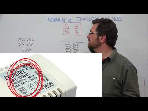
- An example illustrates that if you input 230 volts into a transformer with specified turn ratios (e.g., 2.30 to 12), it indicates how much voltage can be expected at various inputs.
- The discussion emphasizes that while increasing input voltage leads to higher output voltages, one must also consider current relationships; doubling input does not necessarily mean doubling output without considering load conditions.
Power Relationships in Transformers
- The power entering a transformer equals the power exiting it. This principle is crucial when calculating currents based on known voltages and resistances within circuits.
- When asked about current at specific voltages (e.g., using an amperage of one), it's important to note that transformers do not operate effectively under direct current (DC); they require alternating current (AC).
Current Transformation Insights
- A common exam question involves understanding why applying DC results in no output from a transformer; transformers rely on changing magnetic fields created by AC for operation.
- To find current values based on power equations: knowing both input and output powers allows calculation of currents through simple algebraic manipulation involving resistance or impedance factors.
Maximum Power Handling Capabilities
- Observations reveal that increasing tension leads to reduced current flow; thus, high-voltage systems typically operate with lower currents due to their design principles.
- Real-world applications highlight maximum tolerable power levels for transformers; exceeding these limits can lead to failures or inefficiencies during operation.
Understanding Electrical Components and Their Specifications
Key Concepts in Electrical Specifications
- Discussion on the limitations of electrical components, specifically mentioning a threshold of 20 units that cannot be exceeded without consequences.
- Explanation of cable specifications, emphasizing the need for thicker cables to handle increased current in secondary circuits.
- Introduction to fuse ratings, highlighting that a fuse rated at 75,000 will blow if current exceeds this limit, ensuring protection against overload.
- Clarification on transformer specifications, noting how voltage levels can change based on input and output configurations.
- Mention of maximum allowable currents and their implications for circuit safety; stresses the importance of proper fuse selection.
Current Ratings and Safety Measures
- Emphasis on calculating appropriate fuse ratings to prevent equipment damage; suggests using a 1 ampere fuse as a safety measure.
- Discussion about the relationship between primary and secondary currents in transformers; highlights potential risks if incorrect fuses are used.
- Importance of understanding maximum voltage thresholds when selecting fuses to ensure safe operation within specified limits.
- Notes on how improper settings can lead to equipment failure or hazards due to excessive current flow through circuits.
Impedance and Frequency Considerations
- Introduction to impedance concepts in audio applications; discusses how frequency variations affect circuit performance.
- Explanation of impedance relationships between different components in a circuit; emphasizes the significance of matching impedances for optimal function.
- Further elaboration on frequency impacts, indicating that mismatched impedances can lead to inefficiencies or signal loss.
Practical Applications and Problem-Solving
- Overview of practical scenarios involving voltage transformations from 220V to 110V while considering impedance factors for effective design solutions.