Cargador Inalambrico | Teoría y Circuito CASERO
How Does Wireless Charging Work?
Introduction to Wireless Charging
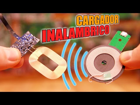
- The speaker introduces a wireless charger purchased from eBay, consisting of a transmitter and a receiver that allows for wireless charging of mobile devices.
- Key questions about the operation of wireless chargers will be addressed, including coil resonance, inductance measurement, power loss, and circuit efficiency.
Understanding Magnetic Induction
- A brief overview of magnetic induction is provided; when voltage is applied to copper wire, it creates a magnetic field around it.
- Wrapping the wire into loops enhances the magnetic field strength at the center due to overlapping fields.
- The principle of Faraday's law states that an alternating magnetic field induces current in a secondary coil.
Inducing Current in Secondary Coil
- Demonstration shows that without changing magnetic flux (e.g., turning on/off the source), no current is induced in the secondary coil.
- To induce current effectively, an alternating magnetic field is necessary; this can be achieved by applying AC voltage to the primary coil.
Practical Experiment with Energy Transfer
- An experiment using a function generator demonstrates energy transfer wirelessly; as proximity increases between coils, an LED lights up without direct connection.
- Challenges arise when trying to connect smartphones directly due to differing voltage requirements and fluctuating output voltages from the secondary coil.
Resonant Frequency and Efficiency
- The importance of resonant frequency for efficient energy transfer between coils is introduced; this involves using an LC tank circuit composed of an inductor (coil) and capacitor.
- Oscillations occur when disconnecting power from the capacitor after charging it; these oscillations' frequency depends on both inductance and capacitance values.
Calculating Inductance and Building Transmitter Circuit
- Instructions are given on how to calculate inductance using an oscilloscope by measuring frequency after connecting a random coil with known capacitance.
- A proposed transmitter circuit design includes a MOSFET for pulsing the primary coil at its resonant frequency while adapting automatically to load changes.
Receiver Design Considerations
- Discussion on receiver design highlights that if both transmitter and receiver coils have equal turns (1:1 ratio), they will produce equal output voltages. More turns are needed for higher output voltages.
Wireless Charging Efficiency and Components
Enhancing Magnetic Field Efficiency
- To improve efficiency in wireless charging, a ferromagnetic material can be added within the loop. For instance, commercial chargers use a metal disk beneath the transmitter coil to better channel the magnetic field.
- The receiver coil is not just a regular tape; it contains a thin layer of ferromagnetic material that interacts with magnets, confirming it's not plastic.
Converting AC to DC
- The output from the receiver remains AC, but devices require DC for charging. Thus, a rectifier made with diodes is essential to convert AC signals into positive pulses.
- Capacitors are added as filters post-rectification to stabilize the DC voltage output. However, variations in voltage occur based on the receiver's position relative to the transmitter.
Maintaining Constant Voltage Output
- A voltage regulator (like AMS1117 or 7805) is necessary to ensure a constant 5V output for smartphones during charging.
- Many smartphones have built-in receivers and coils; however, external receivers can be used by connecting them via USB and placing them under phone cases.
Understanding Transmitter Functionality
- The transmitter receives 5V input from USB and utilizes a microcontroller or driver for enhanced efficiency rather than relying solely on an oscillator.
- When no compatible load is detected, the transmitter emits small pulses every second to conserve energy. Upon detecting a receiver, it oscillates continuously.
Frequency Detection Mechanism
- The frequency of resonance changes when coupling occurs; initially at 220 kHz but drops to around 107 kHz when connected with the receiver.
- A microcontroller on the PCB detects these frequency changes and activates oscillation accordingly while minimizing energy consumption in standby mode.
Circuit Design Insights
- The simplicity of both homemade and commercial circuits lies in their design; differences mainly include advanced components like microcontrollers.
- The compactness of modern PCBs allows for efficient designs with minimal thickness while housing essential components like rectifiers and regulators.
Efficiency Challenges in Wireless Charging
- Measuring energy input versus output reveals significant losses due to inefficiencies ranging from 60% to 80%, leading to slower charging processes.
- Using wireless chargers limits battery capacity utilization since they draw more power compared to wired alternatives.