Astable 555 timer - 8-bit computer clock - part 1
Introduction to Clock Circuit using 555 Timer
In this section, the speaker introduces the use of a 555 timer as a flexible and adjustable clock circuit for computers. The components and connections of the circuit are explained.
Building a Clock Circuit with 555 Timer
- The 555 timer is chosen for its flexibility and adjustability in controlling the speed of the clock circuit.
- Pin configuration of the 555 timer is described, with pin 1 being identified by a divet.
- Powering the chip with 5 volts from a cell phone charger is demonstrated, with pin 8 connected to the positive terminal and pin 1 connected to ground.
- Timing control is achieved through two resistors and a capacitor. A 1k ohm resistor connects pin 7 to the power supply, while a 100k ohm resistor connects pin 7 to pin 6. Pin 6 is then connected to pin 2, which is grounded through a capacitor (1 micro farad).
- The output of the chip is on pin 3, which drives an LED. A current limiting resistor (220 ohms) is used to prevent damage to the LED.
Understanding the Operation of the Circuit
This section focuses on understanding how the components inside the triple five (555) timer work together to generate clock signals.
Exploring Internal Components
- The datasheet for the triple five (555) timer provides detailed information about its internal structure.
- Block diagrams are presented in different formats, but they lack clarity in explaining component connections.
- An alternative diagram created by the speaker illustrates key components more clearly:
- Two comparators
- An SR latch
- Inputs and outputs
Voltage Dividers and Comparators
- The three resistors inside the timer (each 5k ohms) form a voltage divider.
- The voltage divider sets up input voltages for the comparators.
- Comparators have a positive and negative input. If the positive input is higher than the negative input, the comparator output is high (5 volts). If it's lower, the output is low (0 volts).
Operation of the SR Latch
This section explains how turning on the clock circuit triggers the SR latch and determines its initial state.
Initial State of the SR Latch
- When power is turned on, assuming all inputs are at 0 volts:
- The first comparator turns on because 0 volts is below 1.6 volts.
- The second comparator remains off as 0 volts is not above 3.3 volts.
- The SR latch is triggered to set mode, turning on its output.
Due to limitations in available timestamps, this summary may not cover all parts of the transcript.
Understanding the Charging Process
In this section, the speaker explains how the charging process works in the circuit.
Charging Process
- Current flows through a 1k resistor, a 100k resistor, and into a 1 microfarad capacitor.
- The voltage on the capacitor starts at 0 volts and gradually increases as it charges.
- When the voltage on the capacitor reaches above 1.6 volts, a comparator turns off and latches its output.
- As the voltage continues to increase, it eventually reaches 3.3 volts, causing another comparator to turn on and reset the latch.
- The output is reset when the voltage hits 3.3 volts.
Discharging Process
This section focuses on how the discharging process occurs in the circuit.
Discharging Process
- When the voltage on the capacitor reaches 3.3 volts, an inverted output turns on and allows current to flow through a discharge transistor.
- Current can now flow through a 1k resistor and discharge to ground.
- The capacitor starts to discharge through a 100k resistor and continues until its voltage drops below 1.67 volts.
- Once below this threshold, another comparator turns on and sets the latch again.
- The discharge transistor is turned off, stopping current flow through it.
Controlling LED Flashing Rate
This section discusses how adjusting component values can control the rate at which an LED flashes in the circuit.
Adjusting Component Values
- The rate at which an LED flashes can be controlled by adjusting resistor values (RA and RB) and capacitor value (C).
- Larger resistors result in slower charging/discharging rates, while smaller resistors lead to faster rates.
- The size of the capacitor also affects the charging time, with larger capacitors taking longer to charge.
- The duty cycle (on/off time) can be adjusted by balancing the charging and discharging times.
Formulas for Charge and Discharge Times
This section introduces formulas provided in the datasheet for calculating charge and discharge times in the circuit.
Formulas for Time Calculation
- Charge time is calculated using the formula RA + RB multiplied by capacitance (C).
- Discharge time is solely based on resistor RB since it only discharges through that resistor.
- Total period is calculated as RA + 2RB multiplied by capacitance (C).
The transcript does not provide specific values for RA, RB, or C.
Understanding the Time Constant
In this section, the speaker explains how the time constant is calculated using resistance and capacitance. The time constant is used to determine the exponential curve of a function.
Calculation of Time Constant
- The time constant is obtained by multiplying the resistance and capacitance values.
- This value helps in understanding the exponential behavior of a function.
Period Calculation
Here, the speaker discusses how to calculate the period based on the time constant. They also mention that some calculations have already been done for convenience.
Calculating Period
- The coefficient needed to convert from time constant to period has been pre-calculated as 139 milliseconds or 0.139 seconds.
- This period determines the flashing rate of an LED.
Verifying with an Oscilloscope
The speaker demonstrates how to verify their calculations by connecting an oscilloscope to observe the output waveform and capacitor charge/discharge.
Verification Process
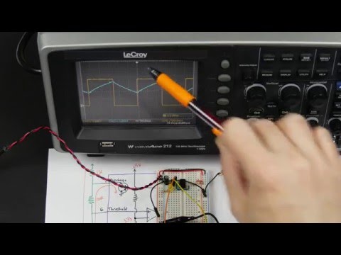
- Connect ground probes and one probe to pin three (output) and another probe to the capacitor.
- Observing the oscilloscope display shows a square wave for output and charge/discharge behavior of the capacitor.
- The voltage range matches expectations, going from approximately one volt up to three volts.
Capacitor Mystery
The speaker discovers an unexpected discrepancy with capacitors labeled as 1 microfarad (MFD). They investigate further using a meter.
Capacitor Measurement
- Capacitors are labeled as 1 MFD (microfarad).
- However, when measured with a meter, they actually measure 2 microfarads.
- This discrepancy affects the calculations, as using the incorrect value leads to a longer period.
Adjusting for Capacitor Discrepancy
The speaker recalculates the period considering the actual capacitance measurement and finds a closer match to expectations.
Recalculating Period
- Since the measured capacitance is 2 microfarads instead of 1 microfarad, it needs to be accounted for in the formula.
- Multiplying the time constant by 2 results in a period of 278 milliseconds.
- The measured period is now closer to expectations at 263 milliseconds.
Noise Reduction Recommendations
The speaker discusses recommendations from the datasheet regarding noise reduction and power supply considerations.
Noise Reduction Measures
- Adding a 0.01 microfarad capacitor from pin 5 to ground helps reduce noise in the transition from 0 volts to 5 volts.
- Further analysis reveals some overshooting during switching due to current requirements not being met quickly enough.
- Additional measures may be required to minimize noise and ensure proper voltage levels.
Conclusion and Power Supply Considerations
The speaker concludes that the circuit is functioning correctly but highlights power supply recommendations mentioned in the datasheet.
Circuit Functionality
- The LED is flashing as expected, indicating correct circuit operation.
- A genuine Apple cell phone charger is used as a power supply, which generally works well.
Power Supply Recommendations
- The datasheet suggests adding a capacitor (0.01 microfarad) from pin 5 (unused) to ground for further noise reduction.
- Some overshooting issues are observed during switching, which may require additional measures for voltage stability.
New Section
In this section, the speaker discusses the impedance of wires and the impact it has on current flow.
Impedance of Wires
- The wire used in circuits has some impedance due to its inductance.
- When current flows through the wire, a magnetic field builds up around it, which resists changes to the current.
- This impedance can affect the performance of the circuit and cause issues with voltage regulation.
New Section
Here, the speaker demonstrates how using a shorter USB cable can improve voltage regulation.
Using a Shorter USB Cable
- By replacing a longer wire with a short USB cable, the impedance is reduced.
- This results in faster response time and better voltage regulation.
- However, there may still be some remaining impedance within other components of the circuit.
New Section
The speaker explores further improvements by adding capacitors to stabilize voltage fluctuations.
Adding Capacitors for Stability
- Placing a capacitor across power connections helps smooth out current transitions.
- A 0.1 microfarad capacitor is added to improve stability.
- The capacitor acts as an additional source of current when needed by the chip.
- Ideally, capacitors should be placed as close as possible to the chip's power pins for optimal performance.
New Section
The speaker explains how to prevent accidental resetting of latch circuits and introduces additional modifications.
Preventing Accidental Resetting
- Pin 4 provides a connection to reset the latch circuit if needed.
- To prevent accidental resets, pin 4 can be connected to 5 volts when not in use.
- This ensures that stray voltages or delays do not trigger unwanted resets.
New Section
The speaker demonstrates how to control the speed of the circuit by modifying resistors.
Controlling Circuit Speed
- By replacing a fixed resistor with a variable resistor, the speed of the circuit can be adjusted.
- A 1 megaohm variable resistor is used for this purpose.
- Adding a 1k resistor in series with the variable resistor prevents short circuits when the resistance is set to its minimum value.
The transcript provided does not include specific timestamps for each bullet point. Please adjust the timestamps accordingly while referencing the transcript.
New Section Understanding the Flickering Effect
In this section, the speaker explains the flickering effect and how it can be controlled using resistors.
The Flickering Effect
- When a resistor is turned all the way down, it causes a flickering effect due to its fast charging and discharging.
- With a 1k resistor, when charging, it goes through 2k of resistors. When discharging, it goes through 1k.
- The speed of the flickering effect can be calculated by doing the math based on the resistance values.
Controlling the Speed
- By adjusting the resistance values, we can control the speed of the flickering effect.
- This control is useful when using it as a clock for a computer or any other application where different speeds are desired.