Vlan Configuration step by step in Cisco Packet Tracer
Introduction to VLANs and Inter-VLAN Routing
Overview of VLANs
- The session focuses on implementing Virtual Local Area Networks (VLANs) using Cisco Packet Tracer.
- VLANs allow network administrators to limit access for specific user groups by segmenting workstations into isolated LAN segments.
- These virtual LAN segments mimic physical LAN characteristics and are configured on switches, creating separate broadcast domains.
Setting Up the Network Topology
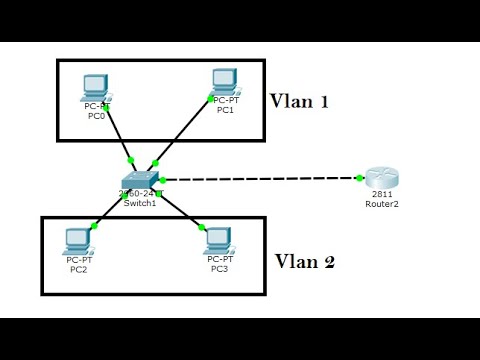
- The tutorial involves creating two VLANs: VLAN 10 and VLAN 20, with four PCs assigned accordingly.
- Two PCs will be part of VLAN 10, while the other two will belong to VLAN 20. A switch and a router will facilitate inter-VLAN routing.
Connecting Devices
- Connections are established using copper straight-through cables from PCs to switch interfaces, ensuring proper configuration for each device.
- The first PC in VLAN 10 is connected via Fast Ethernet interface 0/1; subsequent connections follow a similar pattern for all devices.
Configuring IP Addresses
Assigning IP Addresses
- The first PC in VLAN 10 is assigned an IP address of
192.168.1.10with a gateway of192.168.1.1.
- The second PC in VLAN 10 receives an IP address of
192.168.1.20, maintaining the same gateway as the first PC.
Configuring PCs in VLAN 20
- For the first PC in VLAN 20, an IP address of
192.168.2.20is set with a different gateway (192.168.2.2).
- The last PC in this segment also gets an IP address of
192.168.2.x, following the same subnet mask and gateway settings.
Switch Configuration
Entering CLI Mode
- Accessing the command line interface (CLI), commands begin with enabling configuration mode for setting up VLANS.
Creating and Naming VLANS
- Two VLANS are created: naming them "HR" for VLAN 10 and "Namespace ID" for VLAN 20 enhances identification within configurations.
Port Configuration
Types of Ports Explained
- There are two types of ports: access ports (for connecting switches to PCs) and trunk ports (for connecting multiple devices like routers).
Assigning Access Ports
- Interface configurations start with assigning access mode to interfaces connected to PCs in their respective VLANS.
Example Commands:
- For interface Fast Ethernet 0/1:
- Switch port mode set to access
- Assigned to VLAN 10 using command syntax:
switchport access vlan 10.
Finalizing Router Connection
Configuring Trunk Port
- Interface between switch and router is configured as a trunk port, allowing communication across multiple networks or devices effectively.
This structured approach provides clarity on key concepts related to configuring Virtual LAN environments using Cisco Packet Tracer while facilitating easy navigation through timestamps linked directly to relevant sections of the transcript content.
Configuring Inter-VLAN Routing
Setting Up Trunk Port for VLAN Communication
- The switch is configured to trunk mode on interface 0/5, which connects to the router. This setup allows multiple VLANs to communicate through a single physical link.
Testing Connectivity Between VLANs
- A ping test is initiated from a PC in VLAN 10 to another PC with IP address 192.168.2.20, which belongs to a different VLAN (VLAN 20). The expected outcome is a timeout due to lack of inter-VLAN routing configuration.
Understanding Inter-VLAN Routing Requirements
- To enable communication between the two VLANs, inter-VLAN routing must be configured on the router. This involves setting up specific commands in the router's CLI.
Configuring Router Interfaces for VLANs
- The configuration begins by accessing the router's CLI and enabling interface fa0/0, ensuring it is operational with the command
no shutdown.
- Next, interface fa0/0.10 is configured for VLAN 10 using encapsulation dot1Q and assigning it an IP address of 192.168.1.x as its default gateway.
Finalizing Configuration for Additional VLAN
- Interface fa0/0.20 is then set up for VLAN 20 with similar steps: configuring encapsulation dot1Q and assigning it an appropriate IP address corresponding to its subnet.
Verifying Successful Configuration