Chiller - Cooling Capacity Control
Chiller Capacity Control
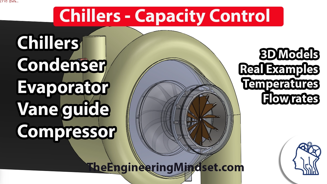
In this video, we will explore chiller capacity control, specifically focusing on vane guides or vane control. We will examine the components of a centrifugal type chiller and how vane guides are used to control the production of chilled water.
Vane Guides in Centrifugal Chillers
- Vane guides are a method of controlling the amount of chilled water produced by a chiller.
- They are located just before the compressor in a centrifugal type chiller.
- The refrigerant gas enters the compressor through the vane guides, which direct and force it into the compression chamber.
- The position of the vane guides determines the flow rate and capacity of chilled water produced by the chiller.
Chiller Operation Overview
- A chiller consists of various components such as the compressor unit, electrical induction motor, evaporator, condenser, and cooling towers.
- The refrigerant gas leaves the evaporator as hot gas and enters the compressor through the vane guides.
- The rotating compressor builds up head pressure and pushes the refrigerant gas into the condenser where it gives up its heat.
- Chilled water is produced in the evaporator and circulated to cool down air in air handling units (AHUs).
- The heat picked up by chilled water is transferred back to the chiller for dissipation in cooling towers.
Understanding Vane Guides and Compressor Components
- Vane guides are triangular-shaped components located inside the compressor that sit directly in the flow of refrigerant gas.
- They can be adjusted to control flow rate and capacity by changing their position.
- When closed, they create a seal that restricts refrigerant flow. When open, they allow more refrigerant to pass through.
- The impeller of the compressor rotates and creates suction, pushing the refrigerant gas out into the volute area.
- The volute builds up the refrigerant gas pressure and forces it down into the condenser.
Visualizing Vane Guides and Impeller
- By removing some components, we can get a closer look at the vane guides and impeller inside the compressor.
- The vane guides have an aerodynamic design that directs refrigerant flow over them.
- When closed, they create a seal with overlapping vanes to restrict refrigerant flow.
- As they rotate together, they open up to allow more refrigerant to pass through.
Conclusion
In this video, we learned about chiller capacity control using vane guides in centrifugal chillers. We explored how vane guides are positioned before the compressor and how their adjustment affects the flow rate and capacity of chilled water produced by the chiller. Understanding these concepts is essential for efficient chiller operation.
This summary covers key points from the transcript related to chiller capacity control using vane guides. It does not include information on other methods or additional details covered in later videos.
New Section
This section explains how the position of the vanes in a chiller affects the flow rate and kinetic energy of the refrigerant.
Vanes Position and Flow Rate
- When the vanes are fully open, the refrigerant flows straight into the impeller without any change in direction.
- As the position of the vanes starts to change, the flow becomes more effective and the refrigerant has to change direction to pass through a smaller gap.
- Changing direction causes the refrigerant to hit the impeller at an angle, reducing its kinetic energy and making it easier for it to flow out of the compressor.
- By adjusting the position of the vanes, we can control the flow rate of refrigerant and reduce its kinetic energy. This affects head pressure and limits heat transfer in the chiller.
Impact on Chilled Water Temperature
- The analogy of driving with your hand out of a car window is used to explain how changing angles affect airflow. As you lower your hand, air rushes across it due to changes in direction.
- Similarly, by changing angles at which refrigerant hits the impeller, we can control its kinetic energy and slow down its flow rate. This raises chilled water temperature leaving the chiller.
- Controlling chilled water temperature is crucial for preventing freezing inside pipes and maintaining optimal performance of chillers.
Capacity Control
- To prevent overproduction or underproduction of chilled water, capacity control is necessary.
- Temperature sensors placed at outlet monitor chilled water temperature leaving evaporator.
- Control unit adjusts vane position based on temperature readings.
- Ensures sufficient refrigerant flow for proper heat transfer and prevents excessive cooling.
- Vane guide design allows chiller to operate at varying capacities, down to 10-20% of its rated thermal load.
- By limiting flow rate, the motor's amps can be controlled, protecting it from damage.
Cooling System Control
In this section, the speaker discusses different methods of controlling the cooling system and provides an example of a set point for outlet temperature.
Controlling the Cooling System
- The cooling oil in the chiller can be used to generate pressure and control the system.
- Alternatively, a small motor can be used to control the system by applying force through a chain or belt.
- Using pressure or a motor is the most common, effective, and reliable way to control the cooling system.
Example: Set Point for Outlet Temperature
- A screenshot from Quetta shows a set point of six degrees for the outlet temperature.
- The water flowing out of the evaporator should ideally be at six degrees.
- The actual temperature is measured at 5.9 degrees Celsius, which is close enough to the set point.
- The incoming water temperature is 11.3 degrees, while the outgoing water temperature is 5.9 degrees.
- The rated load amperage (R-LA) is currently at ninety percent.
- Vane guides are used to control and maintain the desired outlet temperature.
Temperature Sensor Placement
This section focuses on explaining how temperature sensors are positioned in relation to chillers and evaporators.
Positioning of Temperature Sensors
- A temperature sensor is placed in the outlet of the chiller's evaporator.
- The sensor measures and monitors the temperature of the outgoing water.
- Although not visible in this video, there are tubes connected to guide airflow within the chiller.
Conclusion
Thank you for watching this video. If you found it helpful, please like, subscribe, and share. Leave your comments below, and I will try my best to answer them promptly.