MASTERCAM TUTORIAL: PROGRAM THE TITAN-1M (OP1) | ACADEMY
Introduction to Programming the Titan 1M
Overview of the Tutorial
- Nicole introduces herself and the purpose of the video, which is to demonstrate how to program the Titan 1M using Mastercam.
Required Materials
- Viewers are advised to download essential files:
- The Titan 1M print used for design.
- A setup sheet containing tool lists and instructions.
- The Mastercam building blocks tool library.
- All necessary files can be found in the related files section of the video.
Importing Files into Mastercam
File Import Process
- Nicole explains how to import a file by navigating through the file menu, selecting 'open', and browsing for the part's location on their computer.
- She notes that if no files appear, it may be due to incorrect file type settings; she changes this setting to view STEP files instead.
Setting Up Machine Parameters
Initial Setup Steps
- After loading the part, Nicole sets up machine parameters by selecting 'default' from a dropdown menu under the mill tab.
- This action creates a machine group where all tool paths and stock information will be organized.
Understanding Tool Paths
Geometry Considerations
- Discussion on two-dimensional (2D) versus three-dimensional (3D) tool paths:
- 2D Tool Paths: Focus solely on selected geometry and set parameters without considering solid models.
- 3D Tool Paths: Utilize rest machining, taking into account previously machined areas and stock material.
Importance of Stock Models
- For effective roughing operations with a 3D opti-rough tool path, creating a stock model is crucial as it defines what material needs removal based on existing geometry.
Creating Stock Models
Establishing Wireframe Geometry
- To create an accurate representation of stock around the part, it's recommended to place new wireframe or solid geometry on its own level for easy toggling during work sessions.
- Nicole demonstrates creating a new level named "stock" for this purpose.
Generating Bounding Box for Stock Representation
Steps in Creating Bounding Box
- Using Mastercam’s wireframe tools, Nicole selects her model to generate a bounding box that represents stock size accurately according to setup sheet specifications.
Orientation Adjustments
- She emphasizes adjusting orientation so that Z points upwards while X aligns with length and Y with width—demonstrating how precise adjustments ensure correct dimensions are maintained throughout programming tasks.
This structured approach provides clarity on each step involved in programming using Mastercam while ensuring key insights are easily accessible through timestamps linked directly back to specific moments in the video transcript.
Mastercam Setup and Stock Model Creation
Overview of the Process
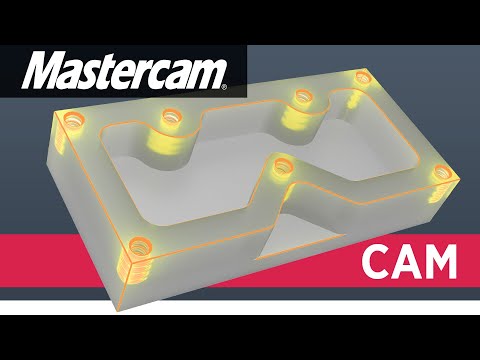
- The process begins with a facing operation, followed by roughing out the outer profile and pockets, and finally adding details like holes, threads, and chamfers using a 3D opti-rough tool.
Setting Up the Stock Model
- The top face of the part is already cut; thus, it's essential to avoid including unnecessary stock material on this surface when setting up the stock model.
- The dimensions for the stock are established: length (X-axis) is set to 4.1 inches and width (Y-axis) to 2 inches, ensuring even material distribution around the part.
- For Z-axis setup, after accounting for previously faced material (0.02 inches), the total height is adjusted to 0.98 inches.
Creating Geometry in Mastercam
- After configuring dimensions, a rectangular solid body representing stock is created; however, Mastercam needs confirmation that this model serves as stock.
- A new stock model is defined in Mastercam by selecting the created geometry and confirming it as an initial reference for toolpaths.
Establishing Workpiece Origin
- To align with machine settings, a new plane must be created in Mastercam that matches X, Y, and Z origins from physical setups.
Importance of Consistency
- The back left edge of the vise is chosen as a fixed point for consistency across setups; this reduces errors during machining operations.
Adjusting Axes Orientation
- Proper orientation of axes is crucial: Z should point up while X runs along length and Y points towards the back. This ensures accurate machining based on consistent references.
Centering Within Stock
- Offsets are applied based on setup sheets to center parts within their respective stocks; adjustments include moving inward by specified measurements on both X (0.05 positive direction) and Y (0.05 negative direction).
Setting Up Machine Origins and Tool Paths
Aligning the Z Origin
- The Z origin is set directly on top of the stock, with an adjustment indicating that the part is 0.02 inches below this point for facing operations.
- The Z origin remains aligned with the top surface of the part, confirming its correct positioning before naming it.
Naming Work Offset
- The new plane is named after the work offset (G54), which will be used in machine programming.
Importing Tool Library
- The tool manager under the toolpaths tab shows default tools; however, a custom building blocks tool library is imported for specific needs.
- Tools are added to the machine group based on a setup sheet, starting with a three-inch face mill as Tool 1.
Organizing Tools
- Each tool's number is adjusted to ensure clarity:
- Tool 2: 3/8 end mill
- Tool 3: quarter inch chamfer
- Tool 4: .1772 drill
- Tool 5: 10-32 tap.
Preparing for Programming
- All tools are now correctly numbered and ready for use in programming. The first tool path selected is a facing operation to establish a reference surface.
Programming First Tool Path
Importance of Facing Operation
- Establishing the top face through facing ensures accurate depth measurements during subsequent operations like pocketing or threading.
Selecting Geometry for Machining
- In the machining setup, solids mode is selected with a focus on facing to choose the entire rectangular boundary of the stock model.
Setting Parameters for Facing Operation
- A three-inch face mill will be used at a feed rate of 25 inches per minute; plunge rate set at 100 inches per minute when not engaged in material.
Efficiency Considerations
- Emphasis on moving quickly when not cutting material enhances efficiency; spindle speed set at 4000 RPM with rapid retract enabled.
Finalizing Cut Parameters
- For cut parameters, one pass is planned due to sufficient width; approach and exit distances are minimized since long overlap provides adequate clearance. Stock-to-leave settings are adjusted to zero for finishing purposes.
Machining Process Overview
One-Pass Finishing Technique
- The machining process involves taking a depth cut of twenty thousandths in one pass across the top surface, emphasizing efficiency by avoiding multiple steps unless more material needs to be removed.
Importance of Absolute Settings
- All parameters are set to absolute based on the work origin, which is crucial for maintaining consistency and clarity during programming.
- Positive numbers indicate safe positions above the part, while negative numbers signify engagement with material or potential crashes, reinforcing the need for careful monitoring.
Reducing Errors through Consistency
- Setting retract heights and feed planes helps ensure that operations remain consistent; retracting to 0.2 inches above the part minimizes risks associated with negative values.
Tool Path Configuration
- For single-pass operations, both top of stock and depth settings are left at zero since they correspond directly to the top surface of the part.
- Verification of all planes against the G54 work offset ensures correct alignment before proceeding with machining tasks.
Coolant and Tool Path Preview
- Ensuring coolant is activated is essential for effective machining; advanced controls beyond this point are unnecessary for basic operations.
- A preview tool path illustrates how the tool will operate: rapid descent followed by a controlled feed rate across the material's surface.
Roughing Out Material
Selecting Machining Geometry
- Transitioning to roughing out material requires selecting appropriate geometry within Mastercam; this step determines what surfaces will be machined.
Wall Stock and Floor Stock Considerations
- Wall stock and floor stock settings dictate how much excess material remains after roughing; these values can vary based on specific project requirements but are set to five thousandths for this tutorial.
Purpose of Rough Cutting
- The goal during rough cutting is to remove bulk material quickly without focusing on final tolerances, allowing subsequent processes to refine dimensions accurately.
Tool Path Control in Mastercam
Setting Up Tool Path Parameters
- The speaker discusses leaving a small amount of material (0.005) on both the wall and floor, resulting in 5000 material remaining at the bottom of the pocket and on all walls.
- A containment boundary is set to define where the tool can travel outside of the part, using boundary chains for selection.
- The outer profile of the part is selected by turning off face filters and focusing solely on edges for accurate boundary definition.
Tool Compensation Settings
- The compensation setting is adjusted to "outside," allowing the tool to travel beyond the selected boundary chain while ensuring that "include tool radius" is checked.
- An offset distance of one inch is chosen to ensure adequate clearance for cleaning up any stock material around the part.
End Mill Selection and Usage
- When programming, it's common to use different end mills for roughing and finishing; however, a single end mill may be used here for simplicity in learning.
- Typically, production parts utilize a roughing end mill pushed harder and faster compared to a finishing end mill which operates at slower speeds for delicate work.
Geometry Considerations
- The internal radii of pockets are noted as 0.195; thus, an end mill with a smaller radius (0.1875) is necessary to clean these features effectively.
- It's emphasized that selecting an appropriate end mill size should consider part geometry, ensuring it fits within internal radii constraints.
Cutting Parameters Configuration
- A feed rate of 25 inches per minute is established along with a plunge rate set at 100 inches per minute; spindle speed is configured at 4000 RPM.
- Rapid retract options are discussed, allowing full-speed retraction when not cutting without needing adjustments in other tabs like holder or stock settings.
Cut Method Preferences
- The cut method is set to climb cutting due to its efficiency on machines and tooling; this technique allows tools to move smoothly against surfaces.
- Climb cutting contrasts with conventional cutting methods where tools push against grain direction, making it more challenging for machines during operation.
Finalizing Tool Path Details
- Default settings are maintained for step-up/step-down optimization but can be adjusted based on machining order preferences if desired.
- Step-over distance is defined as 10% of tool diameter (0.0375), while step-down depth will reach slightly below the part thickness (set at 0.76).
Toolpath Configuration and Finishing Techniques
Toolpath Parameters Setup
- The speaker discusses the importance of maintaining a clearance between the hat left over on stock and the finished walls, setting a step-up value at 0.05 to ensure it is smaller than the distance from the bottom of the part to the smallest step.
- The minimum tool path radius is set to default (20% of tool micro lift distance), which determines how tight corners can be cut. A micro lift distance of 0.01 is deemed sufficient for this operation.
- Back feed rate during lifting is set at 100 inches per minute, ensuring efficient movement without excessive lifting; retract settings are adjusted to "never" to keep the tool down in cuts.
- The entry method for transitions is specified as "helix only," with a helix radius of 0.15, ensuring it’s slightly smaller than the tool's radius for effective cutting.
- Plunge angle is set at two degrees, allowing for gradual ramping into cuts; adjustments can be made based on feed rates if necessary.
Depth and Linking Parameters
- Minimum depth for stock leave is set to zero (top surface), while maximum depth allows cutting up to negative 0.76, enabling slight penetration below the part's bottom surface.
- Clearance plane established at 0.2 ensures safe operation above surfaces; full vertical retract option selected for safety during movements across different surfaces.
- Linear entry and exit parameters are configured with no vertical or linear movements before arcing into cuts, promoting smooth transitions into operations.
- Horizontal arc entries and exits are both set at a lead-in radius of 0.2, facilitating seamless integration into cuts without unnecessary complexity in motion paths.
Finalizing Toolpaths
- In preparation for finishing operations, all settings are confirmed under G54 coordinates; coolant settings adjusted to "on" for optimal machining conditions during cutting processes.
- Visualization confirms that initial spiral down will occur until reaching pocket depth before transitioning to outer profile cutting tasks effectively.
- After roughing out pockets and profiles, focus shifts towards finishing techniques starting with outer profile contours using a designated 2D menu selection method.
- Careful selection of edges ensures accurate contouring around parts; emphasis placed on avoiding incorrect selections that could affect milling directionality negatively.
- Feed rate adjustment down to 20 inches per minute enhances finish quality during final passes; slower speeds contribute positively towards achieving desired surface finishes in machined parts.
Tool Path Setup and Parameters
Setting Plunge Rate and Spindle Speed
- The plunge rate is set to 100 inches per minute, with a spindle speed of 4000 RPM. It's crucial to check the rapid retract settings without altering the holder tab in cut parameters, especially since this is a finishing tool path.
Tool Compensation Settings
- The compensation type is set to "wear," allowing for real-time adjustments of the tool diameter directly at the machine controller. This eliminates the need for program tweaks and reposting.
- Adjustments can be made either positively or negatively to achieve desired part dimensions, ensuring compliance with print specifications.
Climb Milling Direction
- For climb milling, compensation direction is set to "left," ensuring that the tool travels around the part correctly.
- The external corner break radius remains at zero since it’s already modeled into the part; stock-to-leave on walls and floors is also set to zero for finishing paths.
Contour Type and Entry/Exit Settings
- A regular 2D contour finishing path will be used, cutting straight down without depth cuts. Lead-in and lead-out settings are adjusted by unchecking "enter and exit at midpoint" to avoid visible tool marks.
- Starting on a corner rather than in the center helps conceal any witness marks from entering/exiting cuts.
Line Type Configuration
- The line type is configured as perpendicular, which many machines require for cutter compensation.
- Both entry and exit lines are set to 0.2 units long with a corresponding radius of 0.2 units, maintaining consistency in approach angles.
Finalizing Tool Path Parameters
Linking Parameters Review
- No changes are needed for breakthrough multi-passes or tabs; all linking parameters remain absolute for clarity regarding positive (above surface) and negative (below surface).
Depth Settings Confirmation
- Retract height is set at 0.2 units above stock, feed plane at 0.1 units, top of stock at zero, while depth extends slightly below the part at -0.76 units.
Coolant Settings Adjustment
- Coolant settings are confirmed with flood coolant turned on before finalizing parameters.
Executing Contour Operations
Selecting Geometry for Contour Cutting
- A new 2D contour operation will be initiated focusing on geometry around a step feature while considering existing chamfer modeling.
Edge Selection Strategy
- Selecting edges carefully determines travel direction; clicking on specific sides influences arrow directionality during contour selection.
Completing Contour Selection Process
- After selecting appropriate edges based on desired travel direction, multiple selections finalize contour geometry before proceeding with tool selection.
Tool Path Setup in Mastercam
Setting Parameters for Contour Tool Path
- The parameters from the last contour tool path are automatically retained, including feed rate set to 20 inches per minute and plunge rate at 100 inches per minute.
- Spindle speed is configured to 4000 RPM with rapid retract enabled; the correct tool is selected without needing adjustments to the holder tab or cut parameters.
- Depth cuts, lead-in, and lead-out settings remain unchanged as they do not affect this specific tool path; entry is set to perpendicular with specified dimensions.
Multi-Pass Configuration
- Multi-passes are necessary due to the distance from the edge to the center being greater than the tool diameter; two passes will be executed with a spacing of 0.2 inches.
- The option "keep tool down" is checked to prevent retraction between passes, allowing continuous operation.
Linking Parameters and Depth Settings
- All linking parameters are confirmed as absolute; retract height is set at 0.2 inches above feed plane while depth is adjusted to -0.5 inches based on print specifications.
- Coolant settings are retained from previous configurations, ensuring flood coolant remains activated during operations.
Back Plotting Tool Movement
- A back plot visualizes the tool's movement through its first pass before transitioning into a second pass while maintaining depth.
Pocket Tool Path Creation
Selecting Pocket Profile
- Initiating pocket creation by selecting the entire profile using shift-click for accurate selection directionality.
Tool Specifications for Pocketing
- The selected end mill size (3/8") has its feed rate set at 20 inches per minute and plunge rate at 100 inches per minute, with spindle speed remaining at 4000 RPM.
Machining Direction and Stock Settings
- Machining direction is configured for climb milling; stock-to-leave settings are zeroed out since this operation focuses on finishing.
Roughing Tab Options
- Parallel spiral path type chosen under roughing options; entry motion set to helix with defined minimum and maximum radius percentages relative to tool size.
Final Pass Adjustments
- Finishing tab specifies one pass with a spacing of .005 inches for cleanup along walls; cutter compensation is adjusted for wear during this final finishing pass.
Machining Process Overview
Setting Up the Pocket Cut
- The size of the pocket is controlled by setting parameters for the last pass around the walls, with a length and radius both set to 0.2 and a sweep angle of 45 degrees for a shallower arc.
- Parameters are copied over to the exit settings; depth cuts and breakthrough settings remain unchanged. The retract height is set to 0.2, while the feed plane is adjusted to a negative value for plunging into the pocket.
- The feed plane is set to -0.4, starting just above the material surface, ensuring that it ramps down closer to the material before cutting into a pocket that is -0.5 deep.
- Coolant settings are adjusted with flood coolant turned on, confirming that all other parameters are correctly set under G54 tolerance.
- Back plotting shows how the tool will drop down and spiral into the cut, finishing up with a final pass around the wall at a 45-degree angle.
Chamfering Process Initiation
- After completing previous machining steps, attention shifts to chamfering; starting with top chamfers using model chamfer selection from the 2D tab.
- Selection of chain geometry begins at corners where tool marks can be hidden; this ensures aesthetic quality in finished parts.
- Internal chamfers avoid tight spaces; selecting edges strategically allows for better tool positioning without compromising space constraints.
Tool Settings for Chamfering
- Tool three (quarter-inch chamfer mill) is selected with specific feed rates: 20 inches per minute for cutting and 100 inches per minute for plunging outside of material.
- Spindle speed remains at 4000 RPM; rapid retract option checked in cut parameters ensures efficient operation during finishing paths.
Finalizing Chamfer Parameters
- Stock-to-leave parameter set to zero since chamfers are modeled in; no need for additional width adjustments unless sharp edges were present.
- Bottom offset greater than chamfer width (set at 0.05), preventing potential lip formation at bottom edges during machining processes.
- Lead-in and lead-out parameters do not require changes; entry points are confirmed on corners where contours were selected earlier.
Adjustments Before Execution
- Length and radius both set to 0.1 with sweep angle maintained at 45 degrees for optimal cutting approach angles as settings are copied over to exit configurations.
This structured overview captures key insights from each timestamped segment of your transcript while maintaining clarity and focus on essential details related to machining processes.
Chamfering and Drilling Techniques in CNC Machining
Setting Up the Tool Path for Chamfers
- The coolant tab is set to "flood" mode, initiating the tool path with a 45-degree angle and a 0.1 radius offset from the edge.
- Observations confirm that the tool's offset aligns well with the chamfer edges, ensuring precision in machining.
- The current tool path is copied to maintain parameters while adapting to new geometry for the bottom chamfer.
- A new chain selection method is employed, focusing on regular edges to ensure accurate cutting direction.
- Clearance settings are adjusted to 0.03 inches to prevent collisions with walls during machining.
Adjusting Parameters for Optimal Cutting
- Tool offsets are fine-tuned to achieve a clean chamfer close to wall boundaries, enhancing machining efficiency.
- After editing parameters, regeneration of the toolpath is necessary; this allows visualization of how the tool will engage with material.
- Back plotting reveals sufficient clearance between the tool and wall, indicating effective parameter adjustments.
Chamfering Holes Efficiently
- With tools ready, focus shifts to chamfering holes using a quarter-inch chamfer drill; this also serves as a spot drill when needed.
- The hole-making process begins by selecting each hole in an efficient left-to-right order for optimal cutting sequence.
- Feed rates are set at 20 inches per minute with spindle speed maintained at 4000 RPM; rapid retract options are enabled for efficiency.
Finalizing Hole Drilling Process
- Since chamfers are modeled into parts, no additional cut parameters need adjustment; settings remain at zero where applicable.
- Linking parameters are confirmed as absolute; clearance is set at 0.2 inches while other defaults remain unchanged.
- Back plotting confirms that drilling operations find precise depths for each hole while maintaining operational efficiency.
Executing Drill Operations
- Following successful chamfering, attention turns towards drilling holes using selected order methodology for consistency in execution.
- A .1772 drill bit is chosen with feed rate adjusted to 18 inches per minute and spindle speed kept constant at 4000 RPM.
Tool Path Programming and Verification
Peck Drilling Cycle Efficiency
- The peck drilling cycle retracts only a small amount (0.1) after each cut, making it more efficient than traditional methods that require full retraction before the next cut.
Tool Parameters Setup
- The peck depth is set to 0.1, with retract height at 0.2 and top of stock at 0, ensuring the tap goes slightly deeper than the minimum thread depth of 0.380 for clean threading.
Depth Considerations
- To accommodate the taper on tap tips, the drill depth is set to -0.580, providing clearance between the tap and drill depths for optimal threading.
Tool Path Simulation
- Back plotting shows that each peck does not fully retract from the hole, confirming efficiency in material removal during simulation.
Tap Tool Path Creation
- A new tool path for tapping is created by copying an existing one; spindle speed is set to 600 RPM based on machine capability to ensure effective tapping.
Feed Rate Adjustment
- The feed rate automatically adjusts with spindle speed changes; no manual adjustments are needed as it's pre-calculated for optimal performance during tapping operations.
Linking Parameters for Tapping
- The tap's depth is adjusted to be about 100 thou less than the drill's depth (-480), ensuring sufficient threading down to a minimum of 380 without overextending.
Final Tool Path Verification
- All tool paths are verified simultaneously to visualize the final product; this step ensures all programmed paths work together effectively before production begins.
Stock Setup for Simulation
- Stock setup involves selecting a previously created model; accuracy can be enhanced by creating specific stock models but defaults suffice for this tutorial.
Visualizing Final Product
- During verification, visibility settings are adjusted to show only tool paths against stock material, simplifying visualization of final results without distractions from workpieces.
Speed Settings During Verification
- Playback speed during verification is maximized to quickly observe roughing and tapping processes; successful completion indicates all parameters function correctly without issues like gouging.
This structured summary captures key insights from the transcript while linking directly back to relevant timestamps for further exploration or review.
Saving an NC File in the Tutorial
Steps to Save the NC File
- The tutorial begins with the user opting to leave all settings at default before proceeding to save their NC file.
- The user is prompted to note the directory where the file will be saved, emphasizing the importance of knowing this location for future access.
- After naming the file (or accepting a default name), the user clicks 'save' to initiate the saving process.
- Following this action, code generation begins, indicating that the system is processing and preparing necessary files.