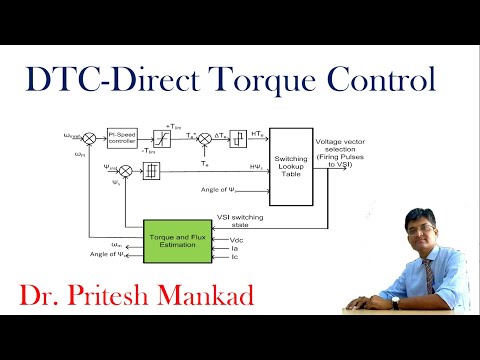
Basics of Direct torque control (DTC) of Induction motor drive
Introduction to Dynamic Modeling and Vector Control of AC Drives
In this section, the lecturer introduces the topic of dynamic modeling and vector control of AC drives. The focus is on discussing vector control and its advantages and disadvantages.
Vector Control Approach
- Vector control assumes two components of the controlling variable: D component (flux direction) and Q component (torque).
- By aligning the flux along the D component and controlling torque along the Q component, flux and torque can be controlled separately.
- This approach allows for fast dynamic response and decoupled control.
Direct Torque Control
- Direct torque control is an alternative method to vector control.
- It is applicable only to induction motor drives operated by a voltage source inverter.
- By controlling the switches in the inverter, a specific voltage space vector can be generated to control torque or flux.
Space Vector Representation
- Space vectors combine three phase vectors (A, B, C) into a single vector representation.
- The combined vector at any instant is given by I_s = A + kB + A^2C, where A is a complex operator.
- This representation allows for easy conversion between individual phase values (ABC) and space vectors.
Introduction to Direct Torque Control Method
In this section, the lecturer introduces direct torque control as an alternative method to vector control. The concept of space vectors or switching vectors is explained as it relates to direct torque control.
Induction Motor Drive with Voltage Source Inverter
- Direct torque control applies specifically to induction motor drives operated by a voltage source inverter.
- By controlling the switches in the inverter, a specific voltage space vector can be generated.
Space Vector Representation
- Space vectors combine three phase vectors (A, B, C) into a single vector representation.
- The combined vector at any instant is given by I_s = A + kB + A^2C, where A is a complex operator.
- This representation allows for easy conversion between individual phase values (ABC) and space vectors.
Direct Torque Control Operation
- Direct torque control aims to control torque or flux by generating specific voltage space vectors.
- By selecting or generating the appropriate voltage vector, a desired value of torque or flux can be achieved.
Understanding Space Vectors
In this section, the lecturer explains the concept of space vectors and their role in direct torque control.
Space Vector Representation
- Space vectors combine three phase vectors (A, B, C) into a single vector representation.
- The combined vector at any instant is given by I_s = A + kB + A^2C, where A is a complex operator.
- This representation allows for easy conversion between individual phase values (ABC) and space vectors.
Reverse Calculation from Space Vector
- Given a space vector I_s, the individual phase values (ABC) can be calculated using real and imaginary parts of I_s.
- Real part of I_s represents the magnitude of phase A. Real part multiplied by A^2 gives phase C. Real part multiplied by A gives phase B.
Three Phase Inverter Operation
In this section, the lecturer explains the operation of a three-phase inverter used in direct torque control.
Three Phase Inverter
- The three-phase inverter consists of six switches arranged in an upper leg and lower leg configuration.
- By controlling these switches, specific voltage space vectors can be generated to control motor operation.
These are the main topics covered in this transcript.
Understanding Switching States and Voltage
This section explains the concept of switching states and voltage in electrical circuits.
Switching States and Voltage
- When switches are on, they create a short circuit, resulting in zero voltage.
- When switches are off, they create an open circuit, resulting in no current flow.
- The voltage across each phase (A, B, C) depends on the DC value of the switch state.
- Different combinations of switch states generate different switching voltage vectors.
Torque and Flux Interaction
This section discusses the interaction between torque and flux in electric motors.
Torque and Flux Interaction
- Torque is determined by the interaction between stator flux and rotor flux.
- Stator flux leads rotor flux by a small angle called gamma.
- Increasing gamma increases torque (proportional to sine gamma).
- Motor control is often done by maintaining constant flux while adjusting torque as needed.
Changing Stator Flux
This section explains how to change stator flux by selecting appropriate voltage vectors.
Changing Stator Flux
- The KVL equation relates applied voltage (Vs), resistance drop (IeSrs), and change in flux linkage (dPhi/dt).
- By neglecting resistance drop, V = dPhi/dt.
- Selecting a proper voltage vector for a fixed interval of time can change the stator flux magnitude or angle.
- Adjusting the stator flux angle affects torque generation.
Increasing Torque through Voltage Selection
This section demonstrates how selecting specific voltage vectors can increase torque.
Increasing Torque through Voltage Selection
- By selecting voltage vectors 1, 2, or 6, the stator flux advances in a specific direction.
- Advancing the stator flux increases the angle between stator and rotor fluxes, resulting in increased torque.
- Selecting voltage vectors that add up to increase the resultant stator flux also increases torque.
The transcript is already in English.
Disadvantages of Jump Stator Flux Control
In this section, the speaker discusses the disadvantages of jump stator flux control and its impact on phase B and phase C. The speaker mentions the requirement of a fast processor for this control method.
Disadvantages of Jump Stator Flux Control
- Jump stator flux control has certain disadvantages.
- It requires a fast processor to handle the control requirements.
- The performance of the system can be affected if the sampling is not done at an appropriate speed.
- Sluggish behavior can occur in certain phases if the sampling is slower or faster than required.
Measurements and Estimations
This section focuses on measurements and estimations in relation to jump stator flux control.
Measurements and Estimations
- In measurements, binary values such as 100100 are used.
- These binary values represent different states or transformations that need to be carried out.
- The top switch being on represents a value of 1, while the bottom switch being on represents a value of 0.
Direct Torque Control Method
The speaker introduces direct torque control as an alternative method to jump stator flux control.
Direct Torque Control Method
- Direct torque control is another method used in motor drives.
- It involves controlling switches to generate specific voltage space vectors.
- By selecting or generating these voltage vectors, it is possible to achieve precise control over torque and flux in an induction motor drive operated by a voltage source inverter.
Space Vector Concept
This section introduces the concept of space vector and its application in direct torque control.
Space Vector Concept
- Space vector refers to combining three vectors: Ia, Ib, and Ic (representing different combinations of switch states).
- By mathematically combining these vectors, a resultant vector known as v1 can be obtained.
- The switching state vector represents the positions of the switches in a two-level inverter.
- Different combinations of switch states result in different switching voltage vectors, which control torque and flux.
Exercise on Space Vector Combination
The speaker presents an exercise for understanding space vector combination.
Exercise on Space Vector Combination
- If there are three vectors: Ia, Ib, and Ic, representing different switch combinations (ABC), they can be combined to form a common vector (Is).
- By controlling the switches, specific voltage space vectors can be generated.
- These switching voltage vectors control torque and flux in motor drives.
The transcript provided is in Spanish.
Understanding the Relationship between Three Factors
In this section, the speaker explains the relationship between three factors and their impact on a system.
Relationship between Three Factors
- When all three factors are active simultaneously, it has a specific effect on the system.
- The knowledge of this relationship can be utilized to achieve desired outcomes.
Stator Flux and Torque Interaction
This section focuses on the interaction between stator flux and torque in a system.
Stator Flux and Torque Interaction
- The location of the stator flux is determined by the position of the rotor.
- By manipulating voltage, one can control whether to increase or decrease stator flux.
- The operation of stator flux is slightly ahead of rotor flux.
- The angle between stator flux and rotor angle affects torque production.
Controlling Torque through Angle Manipulation
This section discusses how torque can be controlled by manipulating angles in a system.
Controlling Torque through Angle Manipulation
- Changing the angle gamma allows for increasing or decreasing torque output.
- Torque is proportional to sine gamma, where 90 degrees represents maximum torque.
- Adjusting the angle gamma enables changing stator currents and voltages to achieve desired torque values.
Motor Control within Limits
This section explains how motor control is achieved while maintaining constant flux within certain limits.
Motor Control within Limits
- Motor control involves maintaining constant flux while adjusting torque as required.
- Flux and rotor flux angles can be changed through a controller to achieve the desired torque.
- Hysteresis band or flux controller is used to regulate the change in torque within a specified range.
Error Correction and Voltage Selection
This section discusses error correction and voltage selection in motor control systems.
Error Correction and Voltage Selection
- Error correction is done by comparing the actual value of flux with the reference value.
- Based on the error, voltage vectors are selected to adjust the magnitude or direction of stator and rotor fluxes.
The transcript provided was in Spanish, so the notes have been translated into English for clarity and understanding.
New Section
This section discusses vector control and direct control methods in electrical drives, as well as the calculations and estimations involved.
Vector Control and Direct Control Methods
- Vector control and direct control are two methods used in electrical drives.
- These methods involve calculations and estimations to determine the switch positions, value of UDC (DC voltage), and other parameters.
- The calculations can be done by PG students or masters students for advanced models, while undergraduate students can calculate D sqs using basic transformations.
- It is important to have a general understanding of these calculations even if all the details cannot be comprehended.
New Section
This section further explains the calculations involved in vector control and direct control methods in electrical drives.
Calculations for Vector Control and Direct Control
- The value of ABCs (switching combinations) can be estimated based on the values of UDC (DC voltage) and which switches are applicable.
- For PG students or masters students, calculating ABC values is possible from known values of UDC. Undergraduate students can calculate D sqs using transformation techniques.
- Resistance may be required for certain calculations, but a general idea about calculation values is sufficient to understand how vector control or direct control measurements are carried out.
New Section
This section discusses the selection of vector control or direct control based on required torque and striking features.
Selection Based on Required Torque
- If X = 1, it means that the required torque is less. In this case, selecting vector control as a major subject would be suitable.
- If X = -1, it means that more torque needs to be produced. In this case, selecting direct control would be appropriate.
- Direct Torque Control (DTC) is a simple method to implement, requiring an increase in switching frequency for faster operation.
New Section
This section explains the control strategy and the selection of voltage vectors for vector control and direct control methods.
Control Strategy and Voltage Vector Selection
- The control strategy determines how the motor parameters, such as flux or torque, are controlled.
- For vector control, if stator flux vector is in Sector 1, fast switching is required. Selecting appropriate voltage vectors allows for quick operation.
- The switching frequency can be variable depending on the requirements.
- V2 represents the top switch in a particular calculation.
New Section
This section discusses the segmentation of the plane into sectors and hysteresis band control.
Segmentation and Hysteresis Band Control
- The plane is divided into 60-degree segments for calculations.
- Each segment represents a different sector with specific characteristics.
- Hysteresis band control involves on/off type switching based on sector positions.
- Two-dimensional plane (dsq S plane) is used for controlling motor performance.
New Section
This section explains how selecting different sectors affects motor performance and requires appropriate switching techniques.
Sector Selection and Switching Techniques
- Selecting different sectors affects talk ripples and requires fast switching for narrow stator flux vectors.
- Choosing suitable voltage vectors enables quick operation and increases controller performance.
- Switching frequency should be adjusted accordingly to achieve desired results.
New Section
This section discusses variable switching frequency and its impact on motor performance.
Variable Switching Frequency
- Variable switching frequency is recommended to optimize motor performance.
- V2 represents a variable that influences controller behavior.
Comparing the Current Situation
This section discusses the current situation and the possibility of making comparisons.
Comparing the Current Situation
- The speaker mentions that something is currently happening.
- The purpose is to compare this ongoing situation with something else.
Timestamp provided in Spanish.