ATR 72 600 Fuel System
Overview of the Fuel System
Introduction to the Fuel System
- The fuel system of the ATR aircraft includes integral wing tanks, a vent system, a fuel quantity indicating system, pump systems, and refuel/defuel systems.
Wing Tanks and Vent System
- Each wing tank can hold up to 2,500 kg of fuel; it features a feeder tank that holds 160 kg and contains an electrically driven fuel pump and jet pump for consistent fuel availability during flight maneuvers.
- A maximum fuel imbalance between tanks is set at 730 kg. Two fuel lines run through the wing center box: one for engine cross-feed and another for left tank refueling.
- The vent system maintains positive pressure in the tanks during aircraft movement; each wing tank has a surge tank with individual vent ducts to prevent vapor concentration and ice accumulation.
Refueling Operations
- Refueling typically occurs via a single-point pressurized system or gravity refueling through caps on top of each wing tank; complete refueling takes about 16 minutes.
- Precautions during refueling include avoiding switch operations (like GPU activation), smoking, and ensuring no thunderstorms are nearby.
Engine Feed System
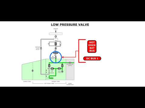
- Each engine receives fuel from its associated feeder tank which is kept full to protect against negative load factors; electrical pumps supply both engines throughout their operational envelope.
- The electrical pump starts automatically if engine jet pump output drops below 5 PSI or if certain conditions like low feeder tank levels occur.
Crossfeed Operations
- A crossfeed valve allows either tank to supply the opposite engine, primarily used for balancing fuel when one side is lower than the other or during single-engine operation.
- To initiate crossfeeding, turn off the pump in the lower-fuel-tank while keeping both electrical pumps running until balance is achieved.
Fuel Quantity Indication System
- The system calculates and displays each tank's fuel quantity based on dielectric constant relationships using capacitance probes; independent channels exist for each wing tank.
- In case of failure in electronic indicators, magnetic level indicators provide ground-level readings accessible from beneath each wing.
Control Panel Functions
- Controls for electrical pumps and crossfeed valves are located on a dedicated panel; pressing buttons activates respective pumps while visual indicators show operational status.
- An amber feed low-pressure light indicates issues with downstream pressure due to potential blockages or failures in both electric pumps.
This concludes the detailed notes on the ATR aircraft's fuel system as outlined in the transcript.
Turn any video into a summary like this
YouTube links, meetings, lectures. With transcripts, search, and chat.