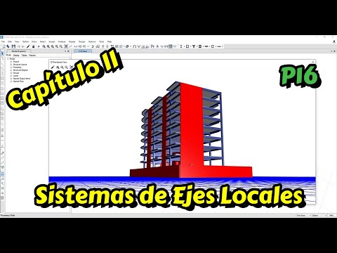
Cap. II - P16: ETABS: Repaso de Elementos Área | Respondiendo Consultas en Vivo
Class Introduction and Confirmation
Initial Setup
- The instructor greets the students and requests confirmation on audio and visual clarity.
- Franklin confirms that both audio and video are functioning properly.
Class Context
- The instructor notes a reduced attendance due to recent holidays, specifically Christmas celebrations.
- Emphasizes the importance of today's class as a review session based on previously uploaded videos about area elements.
Overview of Upcoming Classes
Class Schedule
- The next class will be held on Saturday, January 4th, with a return to regular activities following the holiday break.
- A detailed schedule is provided for upcoming classes, indicating that Chapter 3 will take approximately four sessions to complete.
Elements Area Discussion
Introduction to Area Elements
- The focus shifts to area elements, particularly slabs (losa), which will be modeled in future classes.
- Generating an area element requires at least four points to create a surface representation.
Local Axes Orientation
- Explanation of local axes orientation in relation to global axes (X, Y, Z). Local axis definitions are crucial for understanding results like moments and shear forces later discussed in the course.
Results Interpretation for Slabs
Reading Results from Slabs
- Four key results must be interpreted from slab elements: Moment 1-1, Moment 2-2, Shear 1-3, and Shear 2-3. These differ significantly from frame elements' results used directly in design calculations.
Transformation for Design Use
- Moments derived from slabs are not directly usable; they need transformation into total moments suitable for design applications through specific tools like section cuts in software programs.
Understanding Moments and Shears
Clarification of Moment Definitions
- In slab analysis, the moment around local axis 2 is referred to as Moment 1 instead of Moment 2 as seen in frame elements; this distinction often confuses students but is essential for accurate interpretation of results.
Relationship Between Moments and Shears
- When analyzing moments within slabs, corresponding shear forces must also be considered since they are interrelated; reading one necessitates understanding the other’s implications on structural behavior.
Element Types: Membrane vs Shell
Comparison of Element Models
- Discussion centers around different element types (membrane vs shell), focusing on their degrees of freedom affecting deformation capabilities—membranes allow movement only within their plane while shells permit more complex deformations including out-of-plane movements.
Practical Implications
- Students inquire about practical applications where one might be preferred over another based on structural requirements such as rigidity or flexibility needed in designs like slabs or basement walls.
Conclusion on Element Selection
- Ultimately emphasizes that choosing between membrane or shell elements depends heavily on project-specific needs rather than one being categorically superior over the other; both have unique advantages and disadvantages depending on context.
Understanding Shell and Membrane Elements in Structural Design
Challenges in Modeling with Different Element Types
- The speaker shares a personal experience of adapting to different modeling requirements in private companies, emphasizing the need to follow specific design norms despite personal preferences.
- An example is given where the speaker had to switch from using shell elements to membrane elements for a project due to company standards, highlighting the importance of flexibility in professional settings.
Mathematical Models and Their Differences
- Two mathematical models are discussed: one using a solid slab (20 cm thick) as a shell and another as a membrane, illustrating that both models can yield similar results despite their differences.
- The speaker explains the process of discretizing shell elements versus membrane elements, indicating that this topic is further elaborated in video part 11.
Advantages of Using River Type Elements
- A question arises regarding the advantages of using River type elements regardless of whether they are modeled as shells or membranes; the primary benefit mentioned is automatic weight calculation for concrete.
- The discussion includes how moments appear in beams when modeling shells, even when theoretically they should not receive loads from certain directions, which leads to deeper insights into structural behavior.
Internal Calculations and Weight Considerations
- The speaker describes how defining an element's properties affects internal calculations within software programs used for structural analysis, particularly focusing on how volume and weight are computed based on defined parameters.
- It’s explained that when defining lightweight slabs (aligeradas), understanding their equivalent thickness becomes crucial for accurate modeling and weight distribution calculations.
Discretization Techniques and Their Implications
- There’s an emphasis on how maintaining an element as either shell or membrane influences its ability to be discretized or exported for further design processes like SAFE software integration. This distinction impacts overall design capabilities significantly.
- The conversation touches upon why it’s essential to consider whether an element behaves more like a shell or membrane during load transfer discussions, affecting how loads are distributed across structural components such as beams and columns.
Addressing Common Misconceptions About Load Distribution
- A common misconception about one-directional slabs is clarified: while theoretical teachings suggest no moments should exist in one direction, practical observations show that there will always be some level of moment present due to real-world conditions affecting load distribution.
- The speaker reassures listeners that encountering unexpected moments does not indicate errors in modeling but rather reflects realistic behavior observed in structural systems under various loading conditions.
This structured summary captures key insights from the transcript while providing timestamps for easy reference back to specific parts of the discussion.
Understanding Spandrel Beams and Coupling Beams
Introduction to Spandrel Beams
- The application of spandrel beams is common in design, particularly when designing coupling walls. This may seem unfamiliar to some who have not designed coupling walls before.
Modeling Techniques
- When modeling a coupling beam, it should be treated as a plate rather than a traditional beam. This approach allows for the application of spandrel techniques to ensure proper design.
Design Considerations
- The concept of coupling beams is further explored in videos 13 and 14, which delve into their structural behavior under various loads.
- Coupling beams must meet specific geometric criteria related to their length-to-height ratio, as outlined in Chapter 21 of the relevant standards.
Characteristics of Coupling Beams
- Unlike regular beams that are primarily governed by flexural forces, coupling beams are predominantly influenced by shear forces. This distinction is crucial for effective design.
Structural Reinforcement
- Special reinforcement configurations (like cross-bracing) are necessary for coupling beams due to the high shear forces they experience from adjacent plates.
Criteria for Identifying Coupling Beams
Defining Features
- Not every beam between two plates qualifies as a coupling beam; it must satisfy specific geometric relationships regarding its dimensions.
Verification Process
- A practical example includes verifying if a beam with a span of 5 meters meets the criteria for being classified as a coupling beam based on its length-to-depth ratio.
Upcoming Lessons on Coupling Beam Design
Course Structure
- An upcoming class will focus specifically on the complete design process for coupling beams, emphasizing practical applications and software usage.
Shear Forces and Internal Stresses
Understanding Internal Forces
- It’s essential to understand how internal stresses develop within walls when subjected to tensile or compressive forces along local axes.
Stress Analysis Techniques
- Different types of internal stresses arise depending on whether the wall is stretched or compressed along its local axes.
Application of Edge Elements in Plates
Importance of Edge Elements
- Edge elements become critical when lateral forces cause compression or tension at the edges of plates. Their necessity can be determined by comparing generated stresses against concrete strength thresholds.
Calculation Methods
- To assess whether edge elements are required, one must calculate stress levels at these edges and compare them with established limits from material standards.
Challenges in Working with Local Axes
Complexity in Design Software
- Many designers struggle with understanding local axes when working with basement walls or liquid-retaining structures due to their complexity in software applications.
Simplified Approaches
- Some practitioners resort to simplified methods using Excel instead of comprehensive software solutions, which can lead to less accurate results but quicker computations.
Discretization Effects on Results
Impact on Computational Models
- Smaller discretization sizes can yield more accurate results; however, there comes a point where increasing discretization does not significantly change outcomes but increases computational load.
Recommendations for Discretization Sizes
- Optimal discretization typically ranges between 0.25m and 0.5m.
- Avoid overly large discretizations (e.g., >1m), which may compromise accuracy without significant benefits.
This structured summary captures key insights from the transcript while providing timestamps for easy reference back to specific discussions within the video content.
Understanding Design Width and Load Distribution
Design Width Considerations
- The standard design width is typically one meter, but it is not mandatory; flexibility in width can be applied based on project needs.
- A narrower design width does not inherently lead to better results or more precise steel distribution; the relationship between width and steel placement is complex.
- Reducing the design width may yield finer moments, but reverting to a standard one-meter width will return similar results as initially calculated.
- The program can analyze any strip width, from 1 mm to larger dimensions, with results dependent on the chosen width.
- It’s recommended to stick with a one-meter standard to avoid confusion during calculations related to displacement.
Load Analysis in Structural Design
- Variations in dead loads due to wall density can significantly affect load distribution across panels, especially when modeled correctly in software like Revit.
- While average building weight is approximated at one ton per square meter, actual weights can vary up to 1.5 tons depending on building category and materials used.
- Differences in dead load concentration within a panel necessitate careful modeling of shell elements for accurate analysis of structural behavior under varying loads.
Shell Modeling Techniques
- Two shells can be modeled within the same panel if they are designed for different dead loads; however, enclosing them with beams is generally advisable for structural integrity.
- Concentrating heavier loads in specific areas without proper support (like beams) could lead to unrealistic deformation patterns during analysis.
Recommendations for Structural Integrity
- For optimal performance and safety, it’s best practice to divide panels using beams rather than relying solely on shell modeling without additional support structures.
- If architectural constraints prevent beam placement, treating the entire panel as uniformly loaded may simplify calculations while ensuring conservative estimates.
Final Thoughts and Course Overview
Class Conclusion and Future Sessions
- The instructor encourages students to review supplementary videos that elaborate on topics discussed during class sessions for deeper understanding.
- Upcoming classes will continue exploring advanced topics over several sessions scheduled throughout January 2025.
- Students are reminded of the importance of setting goals for the new year while also preparing adequately for upcoming coursework.