DDCA Ch4 - Part 7: FSMs
Describing Finite State Machines in SystemVerilog
In this section, the speaker discusses how to describe finite state machines (FSMs) in SystemVerilog. They explain the components of an FSM in SystemVerilog and compare Moore and Mealy FSMs.
Components of Finite State Machines
- The speaker explains that both Moore and Mealy FSMs consist of three logic blocks: next state logic, output logic, and the state register.
- Using a divide by three counter as an example, they illustrate the transitions between states on clock edges.
- Transitioning from state s0 to s1 to s2 is demonstrated with corresponding outputs for each state transition.
Frequency Division in FSMs
- The frequency division concept is introduced based on the clock period increasing by 3x, resulting in a frequency divided by a third.
- The calculation of frequencies for input and output signals is explained using specific time periods.
Implementing FSM in Hardware using SystemVerilog
This section delves into converting a state transition diagram into an FSM using SystemVerilog. The process involves defining modules, inputs, outputs, and states within the code structure.
Defining Finite State Machine Module
- The speaker introduces a module named "divided by three fsm" with inputs for clock and reset along with a single output q that asserts every third cycle.
- They define the initial state as s0 where q asserts, followed by transitions between states based on specific conditions.
Implementing State Logic
- A new type called "state type" is defined to represent different states (e.g., s0, s1, s2), simplifying coding by using symbolic representations instead of binary values.
- Assignments for current state (state), next state (next_state), and defining the three logic blocks (state register, next state logic, output logic) are detailed.
Next State Logic and Output Logic
- The functionality of the state register in updating current states based on clock edges or reset signals is explained.
- Next state logic involves determining transitions between states based on current conditions while ensuring determinism through default statements.
Detailed Analysis of Finite State Machines
In this section, the speaker delves into the intricacies of finite state machines (FSMs), highlighting examples and explaining their design in hardware description language (HDL).
Understanding FSM Errors and Design
- When a FSM is designed incorrectly, it may only assert in one state instead of multiple states, leading to errors.
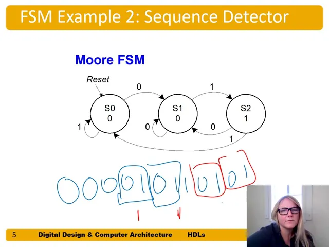
- The sequence detector for detecting "zero one" sequences involves transitioning between states based on input patterns.
Designing FSM in HDL
- FSMs need to detect specific input sequences; for instance, triggering an output when detecting "zero one" patterns.
- Transitioning from a state transition diagram to system Verilog involves defining logic blocks like state register, next state logic, and output logic.
State Register and Next State Logic
- The state register size depends on the number of states required; additional states necessitate more bits for representation.
- Next state logic determines transitions based on current states and inputs, ensuring deterministic behavior with default states included.
System Verilog Implementation of FSM
This segment focuses on implementing a finite state machine using System Verilog, emphasizing efficient coding practices and maintaining deterministic behavior.
Implementing Sequence Detector in System Verilog
- In a Mealy type FSM for "zero one" sequence detection, immediate output assertion upon detecting the pattern differs from Moore type FSM timing.
- System Verilog module conversion involves mapping state transitions directly without explicit circuit design steps.
Coding Next State Logic and Output Logic
- Defining the state register size based on the number of states required simplifies implementation in System Verilog.