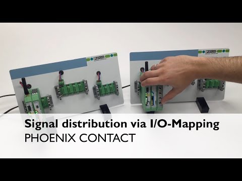
Radioline – I/O-Mode – Signal distribution via I/O-Mapping (Point-to-Point)
Introduction to Radioline Wireless System Setup
Overview of the Setup Process
- The video demonstrates a software-free start-up of the Radioline wireless system in I/O-Mode, focusing on hardware connections and configurations.
- DIN rail bus connectors are attached to the mounting rail as the first step in setting up the system.
Addressing Wireless Modules
- The master wireless module is assigned address "01", while slave or repeater modules can use addresses ranging from "02" to "99".
- Unique RAD-IDs are crucial; duplicate IDs will cause network malfunctions.
Connecting I/O Modules
Digital Input and Output Module Configuration
- A digital output module is connected on the repeater/slave side, with a white thumb wheel used for setting the I/O-MAP address.
- Both input and output modules share the same I/O-MAP address, which is set to "01" in this instance.
Establishing Wireless Communication
Scanning and Configuration
- Upon powering up, the Radioline head station scans for connected I/O modules and reads their thumbwheel addresses.
- Automatic establishment of wireless connections occurs due to default configurations; it’s advisable to adjust RF parameters using a CONF STICK or free software before deployment.
Confirming Successful Communication
Indicators of Operational Readiness
- Successful communication is indicated by bar graph LEDs on the wireless module; operation readiness is confirmed when the red Error LED stops flashing.
- Once operational, digital inputs can be transmitted to assigned outputs using identical I/O-MAP addresses.
For further assistance regarding Radioline systems, contact Technical Service at 800-322-3225.