Curso SolidWorks Piezas y Ensamblaje Lección 13 Ensamble válvula de bola.
Introduction
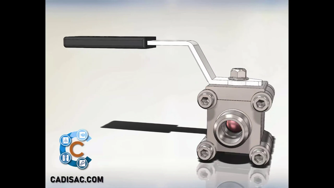
In this session, the focus is on creating an assembly with limited movement in SolidWorks. The goal is to restrict the rotation of a crank by 90 degrees as if there were a mechanical stop. All previously created parts are required for this assembly.
Creating the Assembly
- Begin by opening a new assembly file and adding the central valve piece as a fixed part.
- Utilize temporary axes to establish positional relationships; these are known as temporal axes.
- Arrange the joints in the valve body using coincident and concentric relationships, followed by positioning the sphere within the body using similar relationships.
- Position the ends of the body with coincident and concentric relationships to enable movement of the rod. Consider hiding or making transparent parts for better visibility.
- Use width relationship to synchronize movements between elements, ensuring alignment between components like sphere and rod.
Finalizing Assembly Details
- Apply parallel relationship between flat faces for securing the crank to the upper face of the body. Implement an advanced position relationship called angle to set specific opening and closing angles.
- Integrate M6 nut as a lock for the crank, establishing concentric and coincident relationships only.
- For adding screws, washers, and nuts, choose manual insertion or utilize Smart Fasteners operation if Turbo add-on is active. Adjust screw length and activate schematic threads for visual clarity.
Completing Assembly
- Place additional hardware manually or through Smart Fasteners operation based on hole locations. Ensure correct placement by adjusting positions manually if needed.