DDCA Ch4 - Part 4: Sequential Logic in SystemVerilog
Sequential Logic in SystemVerilog
In this section, the discussion revolves around specifying sequential logic in SystemVerilog using idioms to describe latches, flip-flops, and FSMs. The conversation delves into the importance of utilizing specific idioms for correct hardware production.
Specifying Latches and Flip-Flops
- The general structure for specifying latches and flip-flops involves an "always" keyword followed by a sensitivity list. Changes in the sensitivity list trigger the execution of statements.
- An example of a D flip-flop is provided where the positive edge of the clock triggers the transfer of data from input D to output Q.
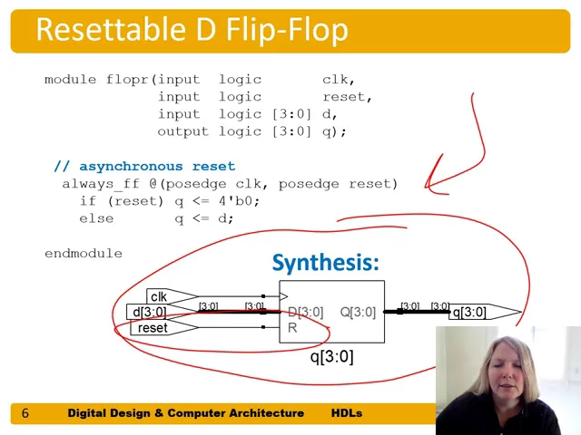
- A resettable D flip-flop is discussed, highlighting how a reset input can alter the behavior of Q based on its value during clock transitions.
Asynchronous vs. Synchronous Resettable Flip-Flops
- The distinction between synchronous and asynchronous resettable flip-flops is explained. A synchronously resettable D flip-flop responds to resets only during clock edges.
- Building an asynchronously resettable flip-flop involves triggering evaluations based on events like a positive edge of both clock and reset signals.
Enable Functionality in Flip-Flops
- Introducing an enable input in a resettable D flip-flop modifies its behavior. When enabled, data transfers from input D to output Q; otherwise, Q retains its previous value.
Latches: Avoiding Errors
This part emphasizes avoiding latch errors by fully specifying combinational logic to prevent unintended latch creation.
Latch Creation Prevention
- Producing latches unintentionally can lead to errors as they retain values when triggered by certain conditions like high clock signals without proper specification.