RC High Pass Filter Explained
RC High Pass Filter Explained
Introduction to RC High Pass Filter
- The video introduces the concept of an RC high pass filter, which allows high-frequency components of an input signal to pass while attenuating low-frequency components.
Frequency Response of Ideal High Pass Filter
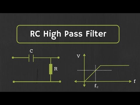
- An ideal high pass filter's frequency response shows that it passes frequencies above a certain cutoff frequency (fc) and rejects those below it.
Circuit Design for High Pass Filter
- By interchanging the positions of the resistor and capacitor from a low pass filter design, one can create a high pass filter. The input is applied at one end, with output taken across the resistor.
Voltage Divider and Output Calculation
- The output voltage (Vout) can be calculated using the voltage divider formula: Vout = R * Vin / (R + Xc), where Xc is the reactance of the capacitor.
Behavior at Different Frequencies
- At low frequencies (w=0), Vout approaches zero due to infinite reactance; as frequency increases, Vout approaches Vin, indicating that higher frequencies are passed through effectively.
Frequency Response Characteristics
Actual vs. Ideal Frequency Response
- In actual filters, at low frequencies, output remains near zero; as frequency increases past fc, output reaches approximately 0.707 times Vin at cutoff frequency.
Cut-off Frequency Equation
- The cut-off frequency (fc) is defined by the equation fc = 1/(2πRC), similar to that for a low pass filter.
Deriving Key Equations
Derivation of Output Voltage Ratio
- The ratio |Vout/Vin| can be expressed as R/√(R² + Xc²). At cutoff frequency, this ratio equals 1/√2.
Simplifying Reactance Terms
- Further simplification leads to R² = Xc²; substituting Xc with its expression results in w = 1/(RC).
Phase Shift Analysis
Phase Change with Frequency
- The phase shift introduced by the high pass filter can be described by tan^(-1)(1/wCR). This indicates how phase changes with varying frequencies.
Phase Values at Specific Frequencies
- At w = 0, phase leads by 90 degrees; at cutoff frequency (wc), it leads by 45 degrees; and at infinity, phase aligns with input signal (0 degrees).
Example Design Problem
Designing a High Pass Filter
High Pass Filter Design and Analysis
Choosing Resistance and Capacitance Values
- The resistance (R) value is critical in high pass filter design; selecting a value in Mega ohms leads to complications due to parasitic capacitance. A recommended range for R is 1-10 kilo ohms.
- The chosen resistance value is 10 kilo-ohms, leading to a calculated capacitance (C) of approximately 1.59 nF using the formula C = 1/2pi R f . A standard capacitor of 1.5 nF will be used for practical purposes.
Cut-off Frequency Calculation
- With R set at 10 kilo-ohms and C at 1.5 nF, the cut-off frequency (fc) calculates to about 10.61 kHz, slightly above the target of 10 kHz.
- To achieve the desired cut-off frequency, a potentiometer (POT) of 20 kilo-ohm will replace the fixed resistor, allowing for fine adjustments to reach exactly 10 kHz.
Frequency Response Characteristics
- When applying a sinusoidal signal of 10 V across the high pass filter, output closely matches input at high frequencies.
- At the cut-off frequency of 10 kHz, output voltage drops to approximately 7.07 V (0.707 times input). At lower frequencies like 1 kHz, output further decreases significantly.
Higher Order Filters
- For designs requiring lower outputs at specific frequencies (e.g., below 700 mV at 1 kHz), higher order filters are necessary due to their steeper roll-off rate of -20 dB/decade.
- Cascading first-order high pass filters can create second-order filters with improved performance; however, care must be taken regarding loading effects between stages.
Isolation Techniques in Filter Design