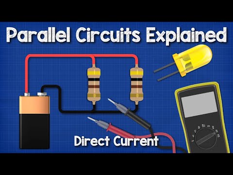
DC parallel circuits explained - The basics how parallel circuits work working principle
Understanding Parallel Circuits
Introduction to Parallel Circuits
- Paul introduces the topic of parallel circuits, explaining their functionality and calculation methods. He mentions that there will be problems at the end for viewers to solve.
Electron Flow vs. Conventional Flow
- The video distinguishes between electron flow (negative to positive) and conventional flow (positive to negative), noting that electron flow is the actual process occurring in circuits.
- In a series circuit, there's only one path for electrons; if one bulb fails, the entire circuit stops working, similar to fairy lights where one broken bulb affects all.
Voltage in Parallel Circuits
- When measuring voltage across components in parallel with a 1.5V battery, it remains consistent at 1.5V due to multiple paths for current.
- Voltage is compared to water pressure; it can only be measured as a difference between two points, similar to how pressure gauges work.
Characteristics of Voltage Measurement
- In parallel circuits, voltage remains constant across all components since each is directly connected to both terminals of the battery.
- This contrasts with series circuits where voltage drops across components due to their sequential connection.
Calculating Voltage Using Ohm's Law
- The formula V = I times R (voltage equals current multiplied by resistance) is introduced for calculating voltage in parallel circuits.
- An example illustrates this: with a total current of 2A and resistance of 3Ω, the voltage calculates as 6V.
Current Flow in Parallel Circuits
Understanding Current Flow
- Current represents the flow of electrons needed to power devices like lamps; applying more voltage increases electron flow without changing their speed.
Measuring Current
- Current is denoted by 'I' and measured in Amperes (or "Amps"). For instance, connecting a lamp with 1Ω resistance to a 1.5V battery results in a total current of 1.5A.
Impact of Adding Components
Understanding Current Flow in Parallel Circuits
Measuring Current Through Individual Lamps
- When measuring current through individual lamps, each lamp reads 1.5 amps, indicating that the total current divides among available paths to return to the battery.
- Replacing one lamp with a two-ohm resistive lamp decreases total current to 2.25 amps; lamp one now sees 0.75 amps and is less bright.
- Lamp two continues at 1.5 amps, demonstrating that branch resistance affects current distribution while total circuit current remains the sum of all branches.
Adding More Components
- Introducing a third one-ohm lamp increases total circuit current to 4.5 amps, with each lamp still receiving 1.5 amps; however, the meter between lamps one and two shows an increase to three amps.
- Doubling voltage from 1.5 volts to three volts results in a doubling of current: total rises to nine amps, with each lamp experiencing three amps.
Calculating Total Current and Resistance
- The relationship between voltage applied and resulting current is emphasized; both are influenced by branch resistance and number of branches connected.
- In a parallel circuit with two resistors (15 ohms and 24 ohms), calculating total current involves summing currents in branches: 0.8 + 0.5 = 1.2 amps.
Finding Currents in Branches
- To find unknown branch currents when total is known, simply subtract known values from the total; for example, if total is three amps and one branch has 1.8 amps, then the other must be 1.2 amps.
Applying Ohm's Law
- The formula for calculating current in a simple branch is introduced: textCurrent = fractextVoltagetextResistance .
- For resistors connected to a six volt battery (10 ohms, 2 ohms, and 5 ohms), calculated currents are:
- Resistor one: 6/10 = 0.6 textamps
- Resistor two: 6/2 = 3 textamps
- Resistor three: 6/5 = 1.2 textamps
Total Resistance Calculation in Parallel Circuits
- The overall approach for calculating total resistance in parallel circuits focuses on how conductive each path is rather than just adding resistances as done in series circuits.
- The formula used for finding total resistance ( R_T = 1/left(frac1R_1 + 1/R_2right)) may seem complex but simplifies calculations significantly.
Example Calculations
- Using two ten-ohm resistors as an example:
- Calculate individual contributions using the formula leading to a combined resistance of five ohms due to split currents reducing overall resistance.
Understanding Conductance and Resistance in Circuits
The Concept of Conductance
- Conductance is introduced as the reciprocal of resistance, highlighting its importance in understanding how electricity flows through various paths.
- The example of a 10-ohm resistor illustrates that conductance can be calculated by inverting the resistance value, resulting in a conductance of 0.1 for this resistor.
- A comparison between different resistors shows that lower resistance (e.g., 1 ohm) leads to higher conductivity, making it easier for electricity to pass through.
Total Conductivity and Resistance Calculation
- To find total conductivity, individual conductances are summed up; the total resistance is then derived by taking the reciprocal of this total conductance.
- Emphasis is placed on using formulas rather than memorizing concepts, simplifying calculations related to power consumption in parallel circuits.
Power Consumption in Parallel Circuits
- Two formulas for calculating power consumption are presented: voltage squared divided by resistance or voltage multiplied by current.
- An example with a 10-ohm and a 5-ohm resistor connected to a 6 volts battery demonstrates how to calculate power consumption (3.6 Watts for R1 and 7.2 Watts for R2).
Total Power Consumption Calculation
- The total power consumed by both resistors is calculated as 10.8 Watts, showcasing different methods to arrive at this figure (voltage multiplied by total current or voltage squared divided by total resistance).
Problem-Solving Exercises
- Two questions are posed regarding resistors in parallel: one asks for the total resistance with four given resistors, while another requires calculating currents and unknown values based on provided data.