What is an Overload Relay? Connection & Working Principle
What is an Overload Relay and How Does It Work?
Introduction to Overload Relays
- An overload relay is a device that protects motors from overheating due to excessive current draw.
- It is essential for industrial automation, ensuring motors do not operate under harmful overload conditions.
Functionality of Overload Relays
- The relay allows temporary harmless overloads (like inrush current) but trips during prolonged excessive current situations.
- When an overload condition persists, the relay sends feedback to the contactor, which interrupts the motor's power supply.
Causes of Motor Overloading
- Common causes include mechanical obstructions, improper shaft alignment, phase failures in three-phase systems, frequent starts/stops, high ambient temperatures, and damaged bearings.
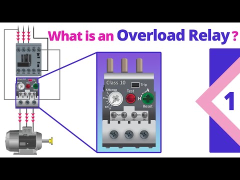
Components of Overload Relays
- Adjustable Current Setting: Allows setting the motor's rated Full Load Amps (FLA).
- Auxiliary Contacts: Includes normally closed (NC) and normally open (NO) contacts that change state during an overload event.
- Reset Button: Can toggle between manual and automatic reset modes after a trip occurs.
- Test Trip Button: Simulates a trip to verify if the relay functions correctly.
- Trip Indicator: Visually indicates when an overload condition has occurred by turning on.
Differences Between Overload Relays and Circuit Breakers
- Circuit breakers protect against sudden high-current events like short circuits by opening instantly; they prevent immediate damage to motors.
- In contrast, overload relays protect against gradual excessive current draw that can deteriorate winding insulation over time; they have a delayed trip characteristic based on their class rating.
Integration with Contactors
- An overload relay must be paired with a contactor; it cannot operate a motor independently but provides critical protection within a motor starter setup.
- Typically positioned beneath the contactor in wiring diagrams, it connects through prongs into load side terminals for effective operation.
Schematic Representation of Operation
- Two symbols represent overload relays in wiring diagrams: NEMA standard uses opposing question marks while IEC standard uses digital pulse symbols for each phase.
Understanding Overload Relay Functionality
Overview of Overload Relay Operation
- The overload relay plays a crucial role in protecting the motor by closing related contacts in the power circuit, allowing current to flow through the overload relay when operating normally without overload.
- In case of an overload condition, the normally closed contact of the overload relay opens, which de-energizes the contactor’s coil and subsequently opens the primary contact in the power circuit, shutting off the motor.
Testing Overload Relay with Multimeter
- To test an overload relay using a multimeter set to Continuity Beeper, ensure continuity between L1 and T1, L2 and T2, and L3 and T3 while in a non-tripped state.
- When testing during a tripped situation, connections between L1 to T1, L2 to T2, and L3 to T3 remain intact; however, auxiliary normally closed contacts will show as open while normally open contacts will indicate continuity.
Upcoming Content