MOSFET, Drivers, Bootstrap - Tipos, Nivel Lógico y más
Understanding N and P Channel MOSFETs
Introduction to MOSFETs
- The video introduces N-channel and P-channel MOSFETs, commonly controlled by an Arduino in various projects.
- It explains the half-bridge configuration of MOSFETs, highlighting the importance of understanding drivers, power dissipation, and gate control.
Key Differences Between N and P Channel MOSFETs
- N-channel MOSFETs typically connect to ground (negative side), while P-channel connects to VCC (positive side), which can lead to circuit issues.
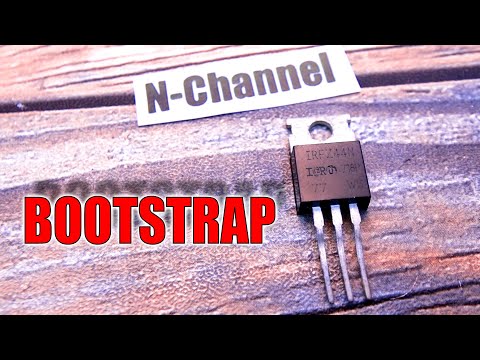
- The IRFZ 44N is presented as a common N-channel MOSFET with specifications: 49A current capacity, 55V voltage rating, but not logic-level compatible for direct Arduino control.
Logic-Level Compatibility
- The IRL Z44N is highlighted as a logic-level compatible option that fully opens at 5V, making it suitable for Arduino projects.
- Other examples include the IRL I244N with isolation features that prevent short circuits when connected directly to metal enclosures.
MOSFET Operation Principles
Operating Characteristics of N and P Channel MOSFETs
- N-channel devices are better suited for low-side switching; they turn on when the gate-source voltage (Vgs) exceeds a certain threshold.
- A pull-down resistor is used on the gate of an N-channel MOSFET to ensure it remains off by default until a positive voltage is applied.
Activation Mechanisms
- Conversely, P-channel devices activate when the gate voltage is lower than the source voltage. They typically use a pull-up resistor connected to VCC.
- This results in different activation signals: activating an N-channel requires a high signal (1), while activating a P-channel requires a low signal (0).
Challenges with High-Power Loads
Power Dissipation Issues
- When using high-power loads with P-MOSFET configurations, higher ON resistance leads to significant power dissipation and potential overheating.
Alternative Solutions
- In some cases, using an N-MOSFET for high-side switching can be beneficial due to its lower ON resistance compared to typical P-MOSFET options.
Bootstrap Circuit Implementation
Addressing Voltage Issues in High-Side Switching
- The bootstrap method is introduced as a solution for driving high-side N-MOSFET configurations effectively.
Understanding MOSFET Control and Bootstrap Techniques
Basics of MOSFET Operation
- The gate of the MOSFET is connected to 0V, keeping it OFF. However, a capacitor charges through a diode to 12V.
- When a LOW signal is applied to the NPN transistor's base, it turns OFF, resulting in a gate-source voltage (GS) of 12V due to the series connection with VCC.
Importance of Bootstrap Circuit
- The bootstrap technique elevates the gate voltage so that GS remains higher than the source voltage, ensuring the MOSFET stays ON.
- For slow switching times, there’s a risk that the capacitor may discharge through resistance or diode leakage, potentially causing malfunction.
Using Dedicated MOSFET Drivers
- Instead of basic circuits, using dedicated MOSFET drivers with internal bootstrap functionality simplifies control. Example: IR2104 driver used in ESC projects.
- The driver connects to both high-side and low-side gates while managing an intermediate position for load connections.
Advantages of Dedicated Drivers
- Dedicated drivers can handle higher voltages (e.g., up to 20V), eliminating logical level issues associated with controlling MOSFET gates directly.