cuatro barras analisis de posición con Geogebra
Introduction to GeoGebra for Four-Bar Mechanism Analysis
Overview of the Tutorial
- The tutorial focuses on using GeoGebra to analyze the position of a four-bar mechanism, previously discussed in class.
- The specific goal is to determine angles θ4 and θ3 when q equals 60 degrees (or 1/3).
Setting Up the Document
- A new document is created in GeoGebra, displaying a grid for drawing.
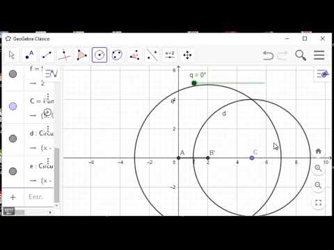
- The first step involves drawing a circle with a center at the origin and a radius of two units.
Defining Points and Sliders
- A point is defined at the intersection of the x-axis and the circle; this will be used for further calculations.
- A slider is introduced to control variable α, which defines angle q, allowing dynamic adjustments during analysis.
Drawing Links and Observing Movement
- Lines representing links are drawn: one for the crank (manivela), another for the coupler (eslabón acoplador), with respective radii of 2, 4, and 5 units.
- The intersections between circles are crucial for defining link lengths; points B, C, D are established based on these intersections.
Measuring Angles
- Angles are measured using GeoGebra's angle tool by selecting three points or two lines; an example gives an angle measurement of approximately 83.89 degrees at q = 76 degrees.
- To measure θ3 from the x-axis, a parallel line through point B is drawn; this results in measuring an angle of approximately 24.32 degrees.
Final Calculations and Verification
- With q set at 60 degrees, calculated values yield θ4 as approximately 83.25 degrees and θ3 as about 26.62 degrees.
- These results are corroborated with analytical methods confirming that θ3 approximates to 26.73 degrees while θ4 remains around 83.25 degrees.
Turn any video into a summary like this
YouTube links, meetings, lectures. With transcripts, search, and chat.