AC Circuit Example 4: Series RLC Circuit
RLC Circuit Analysis: Understanding Impedance and Power
Introduction to the RLC Circuit
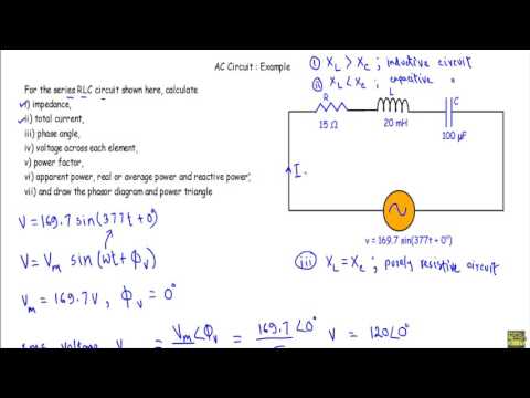
- The video introduces a series RLC circuit consisting of a 15 mΩ resistor, a 20 mH inductor, and a 100 µF capacitor connected in series. An alternating voltage V = 169.7 sin(377t + 0^circ) is applied.
Calculating Key Parameters
- The objective includes calculating total impedance, total current, phase angles across each element, power factor, apparent power, real power, reactive power, and drawing the phasor diagram and power triangle.
Voltage Characteristics
- The maximum voltage V_m = 169.7 textV has a phase angle of 0^circ . The RMS value of the voltage is calculated as V_RMS = V_m/sqrt2 = 120 textV .
Angular Frequency and Frequency Calculation
- The angular frequency omega = 377 textrad/s , which corresponds to a frequency of f = 60 textHz .
Reactance Cases in RLC Circuits
- Three cases for reactance are discussed:
- Inductive reactance ( X_L > X_C ): Circuit behaves inductively.
- Capacitive reactance ( X_L < X_C ): Circuit behaves capacitively.
- Resonance condition ( X_L = X_C ): Circuit becomes purely resistive.
Calculating Impedance
Total Impedance Formula
- Total impedance for an RLC circuit is given by Z = R + j(X_L - X_C) .
Inductive Reactance Calculation
- Inductive reactance is calculated as X_L = 2pi f L = 7.54,Omega.
Capacitive Reactance Calculation
- Capacitive reactance is calculated using the formula X_C = 1/2pi f C = 26.54,Omega.
Final Impedance Values
- Total impedance in rectangular form:
- Z = 15 + j(-19)
- In polar form:
- Magnitude: |Z| ≈ 24.21,Omega, Phase angle: -51.71^circ.
Current Calculation
Alternating Current Determination
- Using Ohm's law for AC circuits:
- Total current calculated as
- I_total = fracV_RMSZ.
Resulting Current Value
- Resulting RMS current is approximately
- I_RMS ≈ 4.96,A,
- with a phase angle of
- Φ_I ≈ 51.71^circ.
Phase Angle Analysis
Phase Difference Between Voltage and Current
- The phase difference between total voltage (Φ_P at zero degrees) and total current (Φ_I at approximately fifty-one point seven one degrees):
- Phase difference (Φ_D):
- Φ_D equals Φ_I minus Φ_P.
Circuit Behavior Insights
Identifying Circuit Type Based on Reactances
- Since inductive reactance (X_L ≈7.54,Ω) is less than capacitive reactance (X_C ≈26.54,Ω), this indicates that the circuit operates capacitively.
Visualizing Waveforms
Sinusoidal Representation of Voltage and Current
- When visualizing sinusoidal waveforms,
- Voltage starts at zero degrees,
- Current leads by approximately fifty-one point seven one degrees.
Power Factor Calculation
Overview of Power Factor in the Circuit
- Discussion on calculating the power factor based on phase differences between voltage and current,
Power Factor and Circuit Analysis
Understanding Power Factor
- The power factor is defined as the cosine of the phase difference between voltage and current, calculated here as cos(51.71°) = 0.62.
- An alternative calculation for power factor involves taking the ratio of resistance (15 ohms) to impedance (24.21 ohms), yielding the same result of 0.62.
Calculating Apparent, Real, and Reactive Power
- Apparent power (S) is computed by multiplying RMS voltage (120V) with RMS current (4.96A), resulting in an apparent power of 595.2 VA.
- Real or active power (P) is calculated using P = V_RMS * I_RMS * cos(Φ), leading to a value of approximately 368.8 W.
- Reactive power (Q) is determined using Q = V_RMS * I_RMS * sin(Φ), which results in a reactive power of about 467.16 VAR.
Power Triangle Representation
- The power triangle visually represents real, reactive, and apparent powers in a right triangle format: real power along the x-axis, reactive power along the y-axis.
- In this circuit analysis, real power is indicated on the positive x-axis while reactive power due to capacitance points downwards on the negative y-axis.
Drawing Phasor Diagrams
- A phasor diagram will be constructed based on voltages across each circuit element; current remains constant throughout a series RLC circuit.
- The reference current vector (I = 4.96A) is drawn along the positive x-direction for clarity in subsequent calculations.
Voltage Across Circuit Elements
- Voltage across the resistor (V_R = I * R = 74.4V); since voltage and current are in phase for resistors, they align directionally.
- For inductive reactance, V_L leads I by 90 degrees; thus V_L calculates to approximately 37.4V at an angle ahead of I.
- Capacitive voltage V_C lags behind current by an angle of -90 degrees; it computes to around 131.64V indicating its phase relationship with respect to current.
Voltage Triangle Analysis
Understanding the Relationship Between Voltages
- The relationship between phase voltage (PL) and circuit voltage (PC) is discussed, indicating that they act in opposite directions. The resultant voltage can be calculated as the difference between PL and PC, leading to a conclusion that PC is greater than VL. This results in a value of 94.24 volts for PC - VL.
- The values of voltages are specified: PL is 37.4 volts, TC is 131.64 volts, and the directional difference represented by the phasor diagram shows PC - VL equals 94.24 volts. This sets up a framework for further calculations involving these voltages.
Constructing the Voltage Triangle
- A vector representation at point P indicates that it corresponds to the difference between PC and PL, reinforcing how these vectors interact within the circuit's context. The hypotenuse of this right triangle represents total voltage in the circuit, which will be crucial for understanding overall power dynamics.
- The magnitude of total power (P) is derived from both VR and the difference (PC - VL). Using Pythagorean theorem principles, it’s established that P will approximate to 120 volts when calculating with PR at 74.4 volts and PC - VL at 94.24 volts, demonstrating how these components contribute to total power output in circuits.
Phase Difference Insights