UD2 Componentes fundamentales de los sistemas microinformáticos 3
Understanding Buses and Expansion Slots in Motherboards
Overview of the Topic
- The video begins by introducing the focus on motherboards, specifically discussing buses and expansion slots as part of a broader topic.
- The discussion is divided into two videos due to the complexity and length of the content.
What are Buses?
- Buses are described as electrical pathways (tracks or lines) that connect various components on a motherboard, facilitating communication between them.
- These tracks transmit binary data (bits), with each line representing either a 1 or a 0 based on electrical voltage levels.
Data Transmission Mechanism
- A bit is identified by its electrical state: high voltage indicates a 1, while no voltage indicates a 0. This simple mechanism underpins data transmission across the motherboard.
- The speed of transmission is notably high; signals travel almost instantaneously along these lines due to their electrical nature.
Types of Data Transfer: Serial vs Parallel
- Understanding different types of data transfer methods is crucial. Buses can operate in either serial or parallel modes.
Parallel Transmission
- In parallel transmission, multiple bits are sent simultaneously across several lines. For example, transmitting an entire byte (8 bits) requires 8 separate lines working in sync.
Serial Transmission
- Conversely, serial transmission sends one bit at a time through a single line. This method often uses two lines for bidirectional communication—one for sending and another for receiving.
Advantages and Disadvantages
- While parallel transmission appears faster because it transmits more bits at once, practical applications show that serial buses have become more prevalent over time due to their simplicity and reduced interference issues.
Interference Issues with Parallel Transmission
- One significant drawback of parallel buses is electromagnetic interference caused by closely packed lines, which can lead to signal degradation at high frequencies.
Conclusion on Bus Usage Trends
Transmission Systems Overview
Types of Transmission Systems
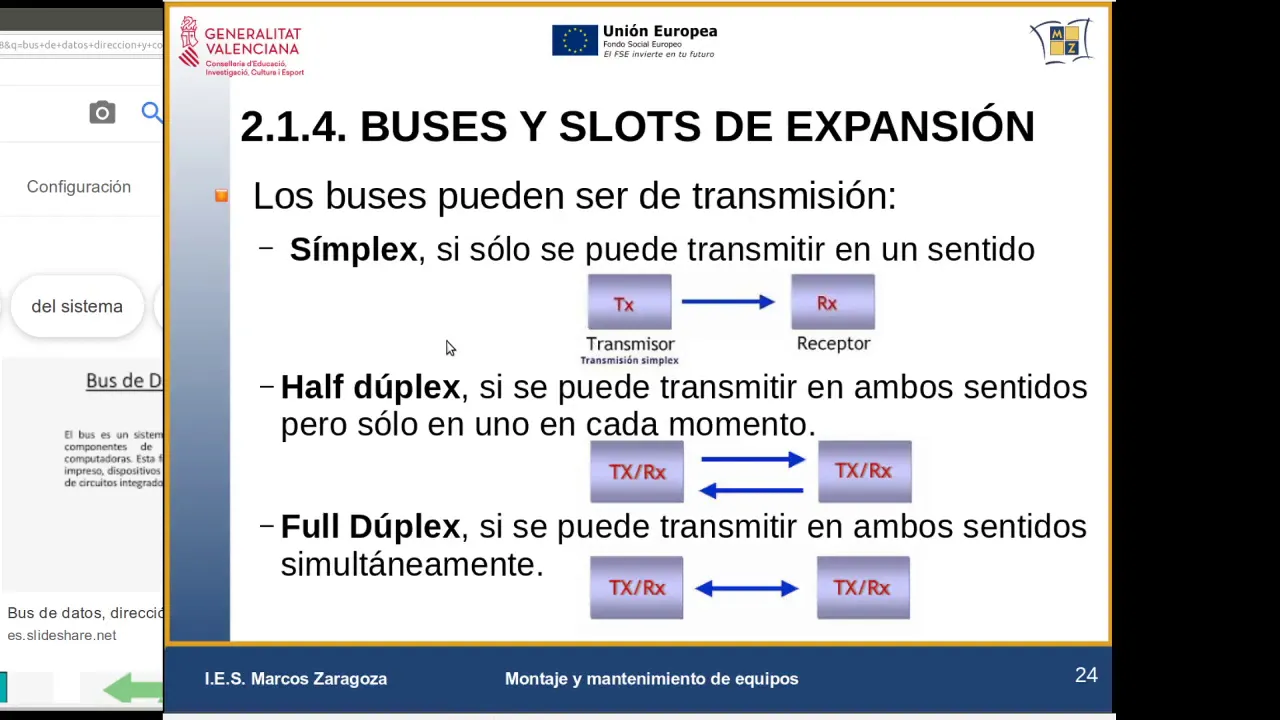
- The distinction in transmission systems is based on the directionality of communication, where a simplex system allows only one-way communication from transmitter to receiver.
- An example of a simplex system is television broadcasting, where the antenna receives signals from a mountain repeater without transmitting any signals back.
Half-Duplex and Full-Duplex Systems
- A half-duplex system allows for two-way communication but not simultaneously; devices take turns transmitting and receiving data.
- In contrast, full-duplex systems enable simultaneous two-way communication, such as in network connections that allow both sending and receiving data at the same time.
Components of Buses in Transmission
- Buses consist of multiple lines that serve different functions: data lines for transferring information, address lines for specifying memory locations, and control lines for managing operations between devices.
Data Lines
- Data lines are specifically used to transfer instructions or data between the CPU and memory. For instance, 64 data lines may be utilized to read bits from memory cells.
Address Lines
- Address lines carry specific memory addresses indicating where data should be read or written. For example, accessing address 1500 requires placing it on the address bus.
Control Lines
- Control lines send commands to other devices regarding what actions to perform with the data and addresses. They facilitate operations like reading from or writing to memory.
Clock Signal
- One important control line is the clock signal (CLK), which synchronizes operations across various components within a computer system.
Understanding Bus Architecture and Clock Signals
Introduction to Bus Systems
- The discussion begins with the importance of understanding internal bus systems, including their operation and functionality.
- A focus is placed on the clock line (clk), which determines the speed of data transmission across buses.
Clock Signal Characteristics
- The clock signal is periodic, meaning it repeats over time at a specific frequency measured in Hertz (Hz).
- Understanding how often this signal repeats per second is crucial for system performance; higher frequencies allow for more operations within that timeframe.
Synchronization and System Activity
- The clock signal dictates the operational pace of devices connected to the bus, ensuring synchronization among them.
- An analogy is drawn between the clock signal's rhythm and a heartbeat, emphasizing that activity occurs only during these 'pulses.'
Measuring Bus Speed
- For example, a bus operating at 1600 MHz can perform 1.6 billion actions per second, illustrating its capacity based on clock speed.
- The relationship between clock speed and overall system performance is highlighted; faster clocks enable quicker data processing.
Visual Representation of Clock Signals
- A visual representation shows how electrical signals toggle between high (on) and low (off), indicating data transmission rates.
- This toggling illustrates how many times signals can repeat within one second, directly correlating to bus speed.
Internal CPU Buses
- Internally, CPUs also have their own buses that influence their operational speeds based on external bus capabilities.
Electrical Signal Changes
- Changes in voltage levels signify when devices can communicate; transitions from low to high voltage represent critical moments for data transfer.
Impact of Clock Speed on Data Transfer Rates
- Higher clock speeds lead to increased data transfer rates across buses due to more frequent signaling changes.
Bus Width: Another Key Characteristic
Definition of Bus Width
- The width of a bus refers to the number of parallel lines available for data transmission; this affects overall throughput significantly.
Parallel vs. Serial Transmission
- In parallel transmission systems, multiple lines transmit bits simultaneously, enhancing transfer efficiency compared to serial methods where bits are sent sequentially.
Calculating Transfer Speeds
Bus Communication and Data Transfer Rates
Understanding Bus Width and Speed
- The bus width determines the amount of data transmitted at once; for instance, a bus with a width of 64 bits transmits one line, which is multiplied by the clock speed to calculate bits per second.
- An example illustrates a bus operating at 100 MHz with a 64-bit data width, resulting in 100 million transfers per second due to the frequency of cycles.
Clock Cycle Dynamics
- Each clock cycle allows for actions to be performed; however, this discussion focuses on complete cycles rather than just rising or falling edges of the clock signal.
- The concept of repetition is introduced: each full cycle (both rising and falling edges) counts as one action. This duality can enhance performance in certain memory types.
Maximizing Data Transfers
- By leveraging both rising and falling edges of the clock signal, it’s possible to double the number of actions taken per cycle, enhancing overall throughput.
- If operating at 100 MHz, theoretically up to 100 million actions (or transfers) can occur every second based on this principle.
Calculating Effective Throughput
- With each transfer sending 64 bits (8 bytes), at a rate of 100 MHz, total throughput can reach up to 800 million bytes per second when calculated correctly.