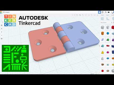
Bisagra Fácil en Tinkercad paso a paso para impresión en 3D
How to Create a Hinge in Tinkercad
Initial Steps for Creating the Hinge
- The process begins by selecting basic shapes: a cylinder, cube, sphere, triangular figure, and cone.
- The first cylinder is adjusted to have maximum sides and a diameter of six. A copy of this cylinder is made with its height modified to two.
- Another cube is created with dimensions of 27 on top and 24 on the side. This shape is aligned with one of the cylinders and moved down by 3 mm before grouping them together.
Further Modifications and Alignments
- The green triangle's width is set to two, rotated 90 degrees, and adjusted to be 15 high and 25 long. The cone's sides are maximized with a height of two.
- Mirror function is applied; the triangle and one cone are aligned on the right axis. Grouping occurs after alignment adjustments.
- Additional alignments are made with another cone while ensuring all figures remain grouped correctly.
Finalizing Shape Dimensions
- Holes for screws or bolts are created as part of the design. A mirrored version of this figure is produced, changing colors for clarity.
- Adjustments continue with another cylinder being modified to a height of 30 mm for hinge measurement purposes.
- An additional sphere is selected, adjusting its dimensions uniformly to create four identical spheres.
Color Coding and Height Adjustments
- Two shapes are centered together; color coding helps indicate which pieces fit together in the hinge assembly.
- For another hinge part, heights are reduced slightly while maintaining consistent diameters across components.
- Grouping continues as elements are aligned properly along axes for cohesive assembly.
Completing the Hinge Design
- Color changes signify which parts belong together; further adjustments ensure proper alignment within the design framework.
- Five segments measuring six mm each are created above existing figures through copying techniques.
- Transparency settings help visualize how different components will interact once assembled.
Final Touches on Assembly
- Remaining parts undergo similar transparency adjustments while ensuring they align correctly within their designated spaces in relation to other components.
Adjusting Figures in Design
Centering and Moving Shapes
- The two figures being discussed measure 30x30 mm each. The speaker centers both figures on the axes.
- The blue figure is then moved 24 mm to the right, demonstrating a practical application of spatial adjustments in design.
- A scale change to 1 mm is mentioned, indicating a shift in measurement precision for better manipulation of the figures.
Visual Changes and Assembly
- The speaker changes the blue figure to a transparent version for visual clarity during the demonstration.