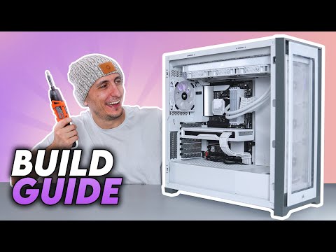
How To Build A PC - Step by Step (Full Build Guide)
Introduction and Overview
In this video, the presenter provides a comprehensive step-by-step guide on building and setting up a PC. The focus is not only on the physical assembly but also on installing the Windows operating system, drivers, and optimizing settings for optimal performance.
Building Your First PC
- Building a PC can be intimidating for beginners, but the presenter assures viewers that they will be guided through each step to ensure everything is done correctly.
- The specific parts used in this build guide are mentioned, but it is noted that different components can be used as well.
- Viewers can follow along with their own PC builds or use the provided link to build an identical PC.
Understanding PC Components
This section provides an overview of the main components found in a PC and their functions.
CPU (Central Processing Unit)
- The CPU is referred to as the "brain" of the PC and is responsible for processing and executing instructions to other components.
- It sits on the motherboard socket.
Motherboard
- The motherboard acts as the backbone of the computer, connecting all components together.
- Different sizes (Mini ITX Form Factor to Extended ATX) and socket types are available.
Memory (RAM)
- RAM is essential for system performance.
- It provides temporary storage for data actively used by applications.
- Higher frequency and lower CL timing are recommended, especially for AMD systems.
Enabling XMP in BIOS
Enabling XMP (Extreme Memory Profile) in BIOS allows memory modules to run at their full speed.
- Many people overlook enabling XMP in BIOS, resulting in memory running at half its frequency by default.
- To check if XMP is enabled, users can go to the task manager, click on performance, and check the memory speed.
- Enabling XMP is crucial for optimal performance.
CPU Cooler
The importance of a CPU cooler in keeping the CPU cool and quiet is discussed.
- Some CPUs come with a cooler included, but if not, it is necessary to choose a capable cooler.
- A good CPU cooler ensures proper cooling and reduces noise levels.
Choosing a CPU Cooler
In this section, the speaker discusses options for CPU coolers and provides recommendations.
CPU Cooler Options
- There are two options for CPU coolers:
- If your CPU comes with a cooler, you can use that.
- Alternatively, if you want something nicer or with RGB lighting, you can purchase a separate cooler.
Recommended Cooler
- The speaker recommends the 'Corsair H150i Elite Capellix', an all-in-one liquid cooler.
- This cooler is visually appealing and will enhance the overall look of the build.
Importance of GPU in Gaming
This section focuses on the significance of the graphics card (GPU) in gaming performance.
Role of Graphics Card
- The graphics card is responsible for providing graphics to your PC.
- It determines how well games run on your PC and affects rendering speed using GPU acceleration.
- A better graphics card results in higher frames per second (FPS) in games and faster render times.
Recommended Graphics Card
- The speaker uses a custom modded 'AMD RX6800' graphics card for this build.
- This card is ideal for gamers looking to play comfortably at 1440p or entry-level 4K gaming.
Choosing a Power Supply Unit (PSU)
This section emphasizes the importance of selecting an appropriate power supply unit (PSU) for your PC build.
Importance of PSU
- The PSU provides power to all components of the PC.
- Using an insufficient PSU can lead to system instability, crashes, and limitations on expandability or overclocking.
Recommended Wattage and Brand
- It is recommended to buy a PSU with at least 100 watts more than what you need to accommodate future upgrades.
- Avoid purchasing cheap power supplies and opt for well-known brands with high efficiency ratings.
Types of Power Supplies
- There are three types of power supplies: non-modular, semi-modular, and fully modular.
- Fully modular power supplies are more expensive but offer the flexibility to use only the necessary cables for your build.
Storage Options
This section discusses different types of storage options for a PC build.
Types of Storage
- M.2 SSDs are small and fast drives, but they tend to be more expensive.
- 2.5-inch SSDs are a good balance between speed and cost.
- Hard drives are slower but cheaper options, suitable for secondary or mass storage purposes.
Recommended Configuration
- It is recommended to have at least one M.2 or traditional SSD as the main drive for faster boot times and application loading.
- Hard drives can be used for secondary storage needs.
Importance of Choosing the Right Case
This section highlights the significance of selecting an appropriate case for your PC build.
Role of the Case
- The case holds all the components together in a stylish manner.
- It also plays a crucial role in providing proper airflow and support for fans and radiators.
Recommended Case
- The speaker uses the 'Corsair 5000 SRGB Full ATX Tower' for this build due to its aesthetics, excellent airflow, and support for various configurations.
Essential Tools and Accessories
This section covers essential tools and accessories needed to build a PC.
Required Tools
- A Phillips head screwdriver is necessary for assembling components.
- An electric screwdriver can provide convenience during assembly.
Additional Accessories
- A magnetic work mat helps keep loose screws organized.
- An empty USB drive with at least 8 GB space is needed to install the Windows operating system.
- A Windows key is required to activate the OS. It can be purchased from various sources, including Yourcdkey.com.
Preparing the Motherboard and Accessories
This section focuses on preparing the motherboard and its accompanying accessories for installation.
Unboxing and Preparation
- Take out the motherboard from its box, ensuring to remove any plastic bags.
- Locate additional accessories such as a front panel connector extension and SATA cables.
The transcript does not provide timestamps beyond this point.
Cables for SSD or Hard Drive Installation
This section discusses the cables needed for installing an SSD or hard drive.
- If you're not installing an SSD or hard drive, you don't need any of these cables.
Removing the 'Wifi Extender' for Motherboards with Built-in Wifi
This section explains the removal of the 'wifi extender' for motherboards with built-in wifi.
- If your motherboard has a built-in wifi, remove the 'wifi extender'.
- The 'wifi extender' is not needed if your motherboard already has built-in wifi.
- The 'wifi extender' is necessary to connect to the internet after building the PC.
M.2 Installation Screw and I-O Shield
This section covers the M.2 installation screw and I-O shield.
- Remove the 'M.2 installation screw' if your motherboard comes with one.
- The 'M.2 installation screw' is required to install an M.2 SSD.
- If your motherboard does not come with an M.2 installation screw, it means that your motherboard already has it installed, so no need to worry about it.
- Check if your motherboard comes with an I-O shield; if it does, you will need it during the PC build process.
- Some motherboards have the I-O shield attached to them.
Manual Removal and Handling of Motherboard
This section discusses removing and handling the motherboard.
- Take out the manual as it can be useful at times.
- Carefully remove the motherboard from its anti-static bag without touching its components on top and back.
- Hold the motherboard from its sides and gently place it on top of the motherboard box to protect it during the installation of CPU, memory, and storage.
CPU Installation Preparations
This section covers the preparations for installing the CPU.
- Open the CPU box and hold the CPU from its sides, avoiding touching its top surface or bottom.
- Most CPUs have a triangle indicating the installation direction on one corner.
- Different CPUs (AMD, Intel, AMD Threadripper) will be installed differently. Skip ahead to the relevant part using timestamps provided in the video.
Installing an AMD AM4 CPU
This section explains how to install an AMD AM4 CPU.
- For an AMD AM4 CPU, locate the golden triangle on the bottom left when looking directly at it.
- Match this triangle with a corresponding triangle cut-out on your AMD motherboard socket's top left corner.
- Lift the lever gently to open it without applying force.
- Lower down the CPU onto the socket without touching its surface or applying force. Gravity should naturally align and seat it properly.
- Check all four sides of the CPU to ensure it is fully seated on the socket.
- Lower down and lock the lever to secure the CPU in place.
Installing an Intel CPU
This section explains how to install an Intel CPU.
- For an Intel CPU, locate the golden triangle (usually at bottom left when looking directly at it).
- Match this triangle with a small triangle cut-out on your Intel motherboard socket cover (in this case, located at bottom left).
- Slide open and lift up the lever while holding onto both sides of the CPU.
- Gently lower down and let gravity align and seat the CPU onto the socket without touching its surface or applying force.
- Lower down the cover and lock the lever to secure the CPU in place.
Installing an AMD Threadripper CPU
This section explains how to install an AMD Threadripper CPU.
- For an AMD Threadripper CPU, use the provided install tool with an orange handle.
- Open the Threadripper box and carefully slide out the CPU without touching its surface or bottom.
- Notice numbers on the socket indicating the order of opening and closing it (3, 2, 1).
- Use a torque driver to loosen screws in that exact order (3, 2, 1) to open the socket.
The transcript ends before further instructions for installing an AMD Threadripper CPU are provided.
Installing the CPU
This section covers the process of installing the CPU onto the motherboard.
Installing the CPU
- Gently slide the CPU against the rails, ensuring a slow and careful movement to prevent it from derailing or popping off the bracket.
- Start from the top and slowly slide the CPU down against the rail until it reaches the bottom.
- Lower the CPU onto the socket while holding down on the blue tabs, ensuring a secure fit.
- Lower and click into place with a 'click' sound.
- Tighten each screw all the way until you hear a 'click'. Apply force if necessary.
Memory Installation
This section explains how to install memory sticks onto a motherboard.
Memory Installation
- Most mainstream motherboards have 4 DIMM slots, one for each memory stick being installed.
- If installing 4 memory sticks, fill up all slots; if installing 2, follow dual channel guidelines for correct slot placement.
- Consult your motherboard's diagram or manual to determine which slots to occupy first for dual-channel configuration.
- Install two memory sticks in slots A2 and B2 for dual-channel configuration.
- Remove tabs on designated slots before inserting memory sticks, aligning gaps on sticks with notches on DIMM slots.
- Apply firm pressure to snap memory sticks into place and ensure tabs are closed.
- Double-check that all memory sticks are properly seated.
M.2 SSD Installation
This section covers the installation of an M.2 SSD onto a motherboard.
M.2 SSD Installation
- Most motherboards have one or more M.2 slots, usually located between PCI slots or behind the motherboard in small form factor boards.
- Install the M.2 SSD on the top slot for optimal placement.
- Decide whether to use the motherboard's cover or an included heatsink for the M.2 SSD; detach heatsink if necessary.
- Use tiny screws provided with the motherboard to unscrew and remove the cover of the top M.2 slot before inserting the SSD into it, aligning notches and gaps correctly.
- If using a motherboard cover, peel off plastic from thermal pad before putting it back on top of the installed M.2 SSD and tightening it back up with screws.
Preparing for Cooler Installation
This section explains how to prepare the motherboard for cooler installation.
Preparing for Cooler Installation
- Different types of coolers (stock AMD cooler or all-in-one cooler) will be demonstrated in this section.
- Most coolers come with pre-applied thermal paste, but if not, it is important to apply thermal paste to the CPU before installing the cooler.
- Two methods of applying thermal paste will be shown.
The transcript provided does not cover the complete video, and additional sections may exist beyond this point.
New Section
In this section, the speaker discusses their favorite method of applying thermal paste and provides instructions on how to do it properly.
Applying Thermal Paste with the Spread Method
- The speaker's favorite method of applying thermal paste is the spread method.
- A thermal paste spatula is needed for this method, which is sold separately.
- Start by applying a small amount of thermal paste in the center of the CPU.
- Use the spatula to evenly spread the paste across the IHS (Integrated Heat Spreader), ensuring full coverage.
- The speaker prefers this method as it provides peace of mind knowing that the entire surface is covered.
Cleaning Thermal Paste from CPU
- If you make a mistake during thermal paste application and need to clean your CPU, use 99% isopropyl alcohol and a paper towel.
- Avoid using tissues or toilet paper as they may leave fibers behind.
- Remove the CPU from the motherboard and add a little bit of isopropyl alcohol to the tip of your paper towel.
- Gently wipe off the thermal paste from the surface of your CPU.
- It's okay if there is some thermal paste left on the sides of the CPU, but you can clean them if desired.
Cleaning Thermal Paste from Cooler
- You can also use a paper towel and isopropyl alcohol to clean off any thermal paste residue from your cooler if necessary.
New Section
In this section, the speaker discusses installing coolers and provides specific instructions for different types.
Installing Stock Cooler (AMD/Intel)
- For AMD motherboards, there are usually two pre-installed brackets that need to be removed before installing a stock cooler.
- Use a Phillips screwdriver to remove all four screws holding each bracket in place.
- Do not remove the bracket behind the motherboard, as it is needed for cooler installation.
- Align the four screws from the cooler with the corresponding holes on the motherboard.
- The same process applies to Intel motherboards using a stock cooler.
- The direction of installation doesn't matter as long as there is clearance, but be aware of potential obstruction by memory sticks.
Tightening Cooler Screws and Cable Management
- Once the cooler is sitting on top of the CPU, tighten all screws in a criss-cross pattern until fully tightened.
- Ensure that all screws are fully tightened before proceeding.
- Plug in the cable coming out of the cooler into the CPU fan header on the motherboard (usually located on the top right side).
- Take this opportunity to manage cables by tucking them underneath the cooler next to RAM sticks for a cleaner look.
New Section
In this section, instructions are provided for installing an AIO (All-in-One) liquid cooler.
Installing AIO Cooler
- Take out the AIO unit and bags of accessories from its box.
- Look for bags labeled with your CPU and socket type (e.g., Intel 1151 or AMD AM4).
- Remove mounting brackets and tightening screws from these bags.
- Locate and uncover the pump of your AIO, being careful not to touch any pre-applied thermal paste.
- If using an Intel CPU, you can keep its bracket on. Otherwise, use brackets specific to your socket type provided in one of the bags.
- Follow any additional instructions provided by your specific AIO model's manual.
New Section
In this section, instructions are given for installing an I/O shield if necessary before placing the motherboard in a case.
Installing I/O Shield
- If your motherboard doesn't have a built-in I/O shield, install it in your case before placing the motherboard.
- No further instructions or details are provided in the transcript beyond this point.
Installing the Motherboard and Fan Configuration
This section covers the installation of the motherboard and provides guidance on fan configuration for optimal airflow.
Installing the Motherboard
- Apply pressure from the inside on all four corners of the motherboard's I/O shield until it snaps in place.
- Remove the motherboard installation screws, ensuring you have one screw for each hole in your motherboard.
- Check if the case has stand-offs installed. If not, install them by placing one stand-off for each hole on your motherboard.
- Lay the case flat on your desk, gently lower the motherboard onto it, aligning the holes with the stand-offs.
- Secure the motherboard to the case using motherboard screws.
Fan Configuration
- Aim for neutral pressure or positive pressure in your case to maintain balanced airflow.
- Fans have arrows indicating their direction of airflow. If no arrows are present, determine airflow direction based on where air is sucked in from (the face of the fan).
- Recommended fan configurations:
- One fan: Place at front for intake and let air escape through GPU and top.
- Two fans: One for intake and one for exhaust (top or rear).
- Three fans: Two for intake and one for exhaust (top or rear).
- Four fans: Two at front for intake and two for exhaust (one top, one rear).
- Five fans: Three at front for intake and two for exhaust.
- Six or more fans: Follow similar concepts to balance pressure in your case.
The minimum recommended number of fans is two – one for intake and one for exhaust.
Fan Configuration with AIO Cooler
This section explains fan configuration when using an All-in-One (AIO) cooler.
- Similar principles apply to AIO coolers, but with the addition of a radiator in front or back of the fans.
- Avoid mounting intake on top due to hot air rising. Intake should be at the bottom, front, or even towards the back in some cases.
- Exhaust fans should be placed at the top or back of your case.
The minimum recommended number of fans for a PC is two – one for intake and one for exhaust.
New Section
This section discusses the different ways to mount an AIO (All-in-One) cooler, focusing on two positions on the top and two positions on the front.
Mounting the AIO on the Top
- The most common and aesthetically pleasing way to install an AIO is on the top of the case.
- The tubes can be positioned to run down from either the right or left side of the case, depending on personal preference.
- It is important to ensure that the tubes from the pump are facing the correct side for optimal performance and longevity.
Mounting the AIO on the Front
- Installing the radiator in front of your case requires careful consideration to avoid damaging the pump and shortening its lifespan.
- Positioning a radiator with tubes coming out from the bottom is considered safe but may not be visually appealing.
- If building a system with a closed side panel case, this method may be recommended as it won't be visible from outside.
- For a more attractive system, it is advised to flip the radiator so that tubes come out from the top. However, it's crucial to ensure that the pump remains below the top of the radiator to prevent air trapping and potential damage.
Recap of Mounting Positions
- Position 1 (top mounting) is considered safest.
- Position 2 (front mounting with tubes at bottom) is acceptable but not recommended.
- Position 3 (front mounting with tubes at top) can damage pump and shorten AIO lifespan.
New Section
This section explores different fan configurations when mounting an AIO cooler.
Fan Placement Options
- Fans can be mounted in either front or back positions, depending on personal preference and case design.
- Push-pull configuration involves using fans both in front and back for optimal cooling performance, if additional fans are available.
Installing Radiator in the Front
- If installing the radiator in the front, it is recommended to install it behind the fans to avoid covering them.
- Some cases have removable brackets that make radiator installation easier.
- Without a removable bracket, carefully remove the front panel and dust filter of the case to access the installation area.
- Temporarily secure fans with longer screws before bringing in the radiator from the back and tightening screws from the front.
Installing Radiator on Top
- When installing the radiator on top of the case, an exhaust fan configuration is ideal.
- Fans should be installed on the radiator first, ensuring cables are positioned towards the back for easy cable management.
- Use longer screws with washers to attach fans to the radiator. Avoid over-tightening.
- Install smaller screws for each fan on top of your case after removing its top panel and dust filter.
New Section
This section provides guidance for installing an AIO cooler based on whether it is mounted in front or on top of a case.
Installing Radiator in Front
- If there are already fans in front of your case, it is advisable to install the radiator at its back to avoid obstructing airflow.
- Removable brackets can simplify this process by allowing easy removal and reinstallation of radiators.
Installing Radiator on Top
- When mounting a radiator on top, an exhaust fan configuration is recommended. The face of fans will be visible from below.
- Begin by attaching fans flat onto the radiator, positioning cables towards the back for better cable management.
- Align fan holes with those on the radiator and use longer screws with washers to secure them. Avoid over-tightening.
- Remove top panel and dust filter (if present) before attaching smaller screws for each fan installed on top of your case.
The transcript is already in English, so there is no need to translate the headings or content.
New Section
In this section, the speaker provides instructions on installing the radiator and A-I-O cooler, as well as connecting cables.
Installing the Radiator
- Once all the cables are through the case, grab onto them from the opposite side and pull on them while bringing in the radiator to prevent any cables from getting stuck inside.
- While holding onto the radiator with one hand, use your main hand to screw it in place.
- Start by tightening one screw on the top left and one screw on the bottom right to hold up the radiator while you finish screwing in the rest of the holes.
A-I-O Installation
- Use two thumb screws and two fisheye screws to install the A-I-O. Insert the fisheye screw from the bottom and thumb screw from the top but don't fully tighten them yet.
- The fisheye part of each screw should lock onto a bracket from the motherboard. Repeat this process for both sides.
- Grab the pump with tubes facing towards the right side and slowly move it close to CPU.
- Tilt the pump towards the top first so that it hooks onto the top bracket, then lower it to hook onto bottom bracket.
- Once both brackets are hooked on, proceed to tighten them evenly.
Cable Connections
- Depending on your A-I-O model, plug cables into appropriate ports. Refer to your manual if needed.
- Plug the shorter thin cable into the motherboard's pump header, if available.
- Plug the fans into the CPU fan header on the motherboard to control their speeds.
- If there is no A-I-O pump header, plug the A-I-O cable into any other fan header and adjust fan settings in BIOS for max speed.
- The thicker cable connects to the 'commander core RGB unit' that comes with the A-I-O. It can support up to six Corsair fans.
New Section
This section covers installing case fans and preparing for power supply installation.
Installing Case Fans
- Use four thicker screws for each fan installation.
- Ensure correct positioning of fans before attaching them to the mounting bracket of your case and screwing them in place from the other side.
- Additional exhaust fans can be added as desired using the same process.
Power Supply Preparation
- Take out the power supply, bag of zip ties, screws, and disconnected cables (if applicable).
- Identify necessary cables. The first one is the 24-pin ATX cable that provides power to the entire board.
- The EPS cable sends power to the CPU socket. Most motherboards have an 8-pin EPS socket located on top left, but some may have additional pins depending on CPU requirements.
The summary provided covers only a portion of the transcript. Please refer to the full transcript for complete information.
[t=0:37:11s] Power Supply Cables Overview
In this section, the speaker discusses the different cables required for a power supply and their purposes.
EPS Cables and PCIe Cable
- EPS cables are recommended to be plugged in if available from the power supply.
- A PCIe cable is needed to provide power to the graphics card.
- The number of pins required for the PCIe cable depends on the connectors on the graphics card.
Optional Cables
- Molex cables are used to supply power to certain devices with 4-pin connectors.
- SATA power cables are commonly used for powering AIO pumps, fan hubs, and storage devices.
- One SATA connector is needed for each SSD or hard drive.
[t=0:38:42s] Connecting Power Supply Cables
This section focuses on how to connect various power supply cables correctly.
ATX Cable
- The 24-pin ATX cable should be connected with the clip facing the hole on the power supply unit.
- The side labeled "PSU" or "type" should be plugged into the power supply unit.
EPS Cables
- The CPU-side labeled cable goes into the motherboard, while the other side plugs into the power supply.
- Ensure that there is a match between the number of pins and holes in both ends of the cable.
Molex and SATA Power Cables
- Molex and SATA power cables plug into peripheral/SATA ports on both ends.
- These connections have 6-pin connectors for easy identification.
[t=0:40:20s] Installing Power Supply in Case
This section covers installing the power supply unit (PSU) in a computer case.
Positioning PSU
- Position PSU so that its fan faces towards case ventilation for proper cooling.
- Consider the clearance for cables and components near the PSU.
Adjusting Hard Drive Cage
- If there is limited space for cables due to the hard drive cage, it can be moved or repositioned.
- Loosen thumb screws to adjust or remove the hard drive cage as needed.
Securing PSU
- Use screws provided in the power supply box to secure the PSU to the case from the back.
[t=0:41:36s] Plugging in Storage Devices
This section discusses connecting storage devices to the power supply.
Preparing for Storage Device Installation
- Before plugging in cables, take this time to select and prepare storage devices for installation.
Connecting Hard Drives
- Understand which cables are needed and how to plug them in correctly.
- Follow specific instructions based on your storage device type (hard drives).
These notes provide a comprehensive summary of the transcript, organized into meaningful sections. Each section focuses on a specific topic related to power supply cables and their installation process. The bullet points highlight key points and insights from each section, with timestamps provided for easy reference.
How to Install Hard Drive and SSD | Step by Step Guide
This section provides a step-by-step guide on how to install a hard drive and SSD into a computer case.
Installing the Hard Drive
- The black SATA cable connects the hard drive to the SATA port on the motherboard.
- The SATA port is usually located on the right edge of the motherboard, underneath the larger 24-pin connector.
- Locate the hard drive cage, typically found at the bottom of the case under the power supply cover.
- Remove one of the hard drive trays from the back of the cage.
- There are two methods to attach the hard drive to the tray: using screws or pegs.
- Using screws: Align four holes on the tray with four holes on the back of the hard drive and secure them with screws.
- Using pegs (preferred method): Insert four pegs attached inside the tray into corresponding holes on each side of the hard drive. Ensure that connectors face towards the back for easy cable connection.
- Slide in and secure the tray back into place within the hard drive cage.
Installing an SSD
- If there are no additional SSD trays, align holes from a regular tray with those on an SSD and screw it in place. Alternatively, use an SSD-specific tray if available.
- In most cases, smaller SSD trays are attached at either back or top of case.
- Securely attach SSD to tray using small screws.
- Connect smaller SATA cable to smaller connection port at back of SSD, and larger SATA power cable to the larger connection.
- Slide the tray back into the case and connect the other end of the black SATA cable to the SATA port on the motherboard.
Connecting Case Cables
- Start with cables from the case, which are often grouped together at the back of the PC.
- Identify and separate cables, beginning with one that connects to USB 3.0 ports on front of case (if available).
- Connect this cable to USB 3.0 header on motherboard, usually located near a 24-pin connector or at bottom.
- Locate audio cable for connecting front audio and microphone jacks from case to motherboard.
- Connect audio cable to corresponding header labeled "JUSB-3" on motherboard, ensuring proper alignment and full insertion.
- If additional USB ports are present on case, connect corresponding USB cable(s) to USB header(s) on motherboard. Match pins with holes and ensure correct orientation.
- If there is a shortage of USB headers, consider purchasing a USB hub extension for extra ports.
Timestamps have been associated with relevant bullet points in accordance with provided transcript.
Connecting the USB-C Cable
In this section, the speaker explains how to connect the USB-C cable to the motherboard.
Connecting the USB-C Cable
- Make sure the pins match with the connector before inserting it in.
- The cable should have its words facing up and be fully inserted into the USB-C header on the motherboard.
- The USB-C header is usually located near the '24' pin or at the bottom of the motherboard.
- The port is labeled as 'USB 3.1' or 'U31'. It can be connected in either orientation.
Plugging in Fans and Fan Hubs
This section covers how to plug in fans and fan hubs, specifically for a Corsair Caplex cooler.
Plugging in Fans and Fan Hubs
- Before moving on to power supply cables, plug in all fans and fan hubs. Skip this step if not using a Corsair Caplex cooler.
- The Corsair Caplex cooler comes with a Commander Core that can accommodate up to 6 Corsair RGB fans.
- Plug in 3 intake fans and 3 exhaust fans into the Commander Core, ensuring that each fan's 4-pin cable connects to one side and RGB cable connects to another side of each fan.
- Connect the thin cable from the pump to the pump header on the motherboard. If no pump headers are available, any fan header can be used.
- The thicker cable from the pump connects to the Commander Core unit.
Connecting the Commander Core
This section explains how to connect and configure the Commander Core.
Connecting the Commander Core
- The Commander Core has two cables attached to it. The USB-labeled cable plugs into the USB header on the motherboard, usually located at the bottom of the board.
- The other cable is a SATA power cable that connects to a female SATA power cable from the power supply.
Alternative Fan Hub Option
If not using a Corsair Caplex cooler, this section provides an alternative option for connecting fans.
Alternative Fan Hub Option
- If not using a Corsair Caplex cooler but still have 6 fans to connect, an integrated fan hub behind the case can be used. It functions similarly to a Commander Core unit.
- Connect all 4-pin fan cables to the fan hub and RGB cables to an RGB hub. Additional case fans should be connected directly to fan headers on the motherboard.
Using Fan Hubs and Recommended Options
This section discusses using fan hubs and recommends options for expanding fan headers.
Using Fan Hubs and Recommended Options
- If more than 5 extra fan headers are needed, a recommended option is to use a fan hub that requires power from a molex cable in addition to connecting to a fan header on the motherboard.
- For up to 5 extra headers, a simpler and cheaper option is available that only requires plugging into a fan header on the motherboard.
- If additional fan headers are required, purchasing a fan hub is recommended.
Connecting Tiny Pins
This section explains how to connect tiny pins from the case.
Connecting Tiny Pins
- The tiny pins plug into the 'JFP-1' header on the bottom of the motherboard, which has 9 pins (4 on top, 5 on bottom). Refer to a diagram for assistance.
- Connect the power LED+ and LED- cables first, followed by the power SW cable for the power switch. Ensure correct orientation and placement of each cable.
- Flip the HDD-LED cable upside down before plugging it into pins number 1 and number 2 from the bottom row.
- Finally, connect the Reset SW cable if applicable, next to the HDD-LED in pins number 3 and number 4 with correct orientation.
Connecting Power Supply Cables
This section covers connecting the main power supply cables.
Connecting Power Supply Cables
- Connect the 24-pin cable to the corresponding socket on the motherboard.
The summary includes only the relevant sections from the transcript and is written in English, as requested.
New Section
This section discusses the proper installation of cables and components in a PC build.
Installing EPS and SATA Cables
- Ensure that the 8-pin EPS socket is properly connected to avoid any issues with the system. If your motherboard has an extra 4-pin connector, you can plug it in as well, but it is not required. You can split one of your EPS cables into dual 4-pin cables if needed.
- If your power supply does not have an extra 8-pin cable, don't worry as your PC will still function normally without it. However, if your motherboard has dual 8-pin EPS connectors and you have an extra cable, go ahead and plug it in for better performance.
- Plugging in storage devices such as SSDs or hard drives requires connecting the SATA power cable to the larger port behind the device and the smaller black SATA cable to the smaller port. The other end of the SATA cable should be plugged into the SATA port on the motherboard, usually located at the bottom right.
- Devices requiring a molex cable should be plugged in at this stage.
- RGB devices need to be connected to either a 3-pin or 4-pin RGB header on the motherboard, ensuring that the number of holes on the cable matches the number of pins on the motherboard.
Installing Graphics Card and PCIe Devices
- Install your graphics card in the highest PCIe slot on your motherboard for optimal performance. Remove any corresponding brackets from the back of the case and slide in the graphics card until you hear a click or feel it lock into place. Use caution when removing a graphics card to prevent damage to locking tabs.
- If your GPU is sagging, support it with your other hand while tightening the thumb screws at the back. PCIe devices like sound cards or SSDs can be installed in available slots by removing the corresponding brackets.
- Connect the appropriate PCIe cables to your graphics card, ensuring that the number of pins on the GPU matches the cables being plugged in. Position the clip towards the lip before connecting and ensure a secure connection.
New Section
This section emphasizes that although all components are connected, there are still important steps remaining.
Final Steps and PC Boot
- Congratulations on completing all component connections! However, there are still crucial steps left to complete.
- Install Windows, download drivers, and enable XMP profile for optimal performance.
- Before focusing on cable management, ensure that your PC boots properly. Plug in the power cable from the power supply into the back of your PC and switch it on using the switch indicator. Connect a monitor via HDMI to your graphics card along with a keyboard and mouse. Do not use a display port cable until after installing drivers. Power on your PC and check if it displays correctly on your monitor; this indicates successful booting.
- If no display appears, double-check all connections and refer back to relevant parts of the video for troubleshooting guidance if necessary.
New Section
This section focuses on cable management techniques.
Cable Management
- Use zip ties or velcro straps to group cables together neatly for effective cable management.
- Disconnect cables as needed and route them in an organized manner.
- Employ various techniques to achieve clean cable management.
- Use zip ties or velcro straps to group cables together.
- Route cables along designated paths or channels in the case.
- Ensure cables are not obstructing airflow or components.
- Take your time to achieve a clean and organized cable management setup.
The transcript is already in English, so there is no need to respond in a different language.
Installing the Operating System and Drivers
This section covers the steps to install the operating system and drivers on a new PC.
Cable Management and Side Panel Closure
- Once satisfied with cable management, close off the back with a side panel.
Preparing for OS Installation
- If using a clear side panel, peel off any plastic beforehand.
- If motherboard has built-in Wi-Fi, plug in the Wi-Fi extender from the back.
- Load the operating system on a flash drive using another device with internet access.
- Visit Microsoft website and download "Microsoft installation media tool". Launch program and follow on-screen instructions, accepting terms.
- Select "create installation media" option and ensure correct language is selected before proceeding.
Installing OS from Flash Drive
- Select flash drive as installation location when prompted during setup process.
- Choose flash drive connected to PC and proceed. Note that this will erase everything from the flash drive.
- Wait for Windows to download OS onto flash drive.
- After completion, remove flash drive from PC.
Powering On and OS Installation
- Plug in USB drive containing OS files into motherboard's USB port.
- Turn on PC; it will recognize the USB drive and take you to installation page.
- Enter CD key if available; otherwise, select "I don't have a product key". Note that Windows activation is required eventually for proper PC usage.
- Choose appropriate version of Windows to install based on your purchased key. For example, select "Windows 10 Pro".
- Accept license terms and select custom option for installation.
Selecting Storage Device
- Choose the storage device (e.g., M.2 or SSD) for OS installation, preferably the fastest drive available.
- Format drives if desired by selecting and clicking on "format" option.
- Proceed with installation and wait for Windows to complete the process, which may take a few minutes up to 30 minutes depending on storage speed. The PC will restart multiple times during this process.
Setting Up Windows
- Follow on-screen instructions to finish setting up Windows, providing necessary information until reaching the desktop screen.
Installing Drivers
- If PC has no internet access, remove USB drive and download drivers onto it from another device with internet access.
- Visit motherboard manufacturer's website and search for your specific motherboard model.
- Go to support or download section and download necessary drivers listed for your motherboard.
- For AMD CPUs or graphics cards, download auto-detect software from AMD's page. For Nvidia graphics cards, download and install GeForce Experience. For Intel CPUs, find chipset driver in motherboard support section.
- Transfer downloaded files to USB drive and plug it into new PC.
- Copy files from USB drive to desktop; do not install them directly from the USB drive.
Conclusion
This section provides final instructions for installing drivers after setting up Windows.
Finalizing Driver Installation
- Install the copied driver files from the desktop onto the new PC.
- Enable XMP profile to optimize performance.
Timestamps are provided in seconds .
Double click the file and extract, if necessary. And once it's done being extracted, double click on the set-up file again, and follow the instructions.
This section provides instructions on how to extract files and run the set-up file.
Extracting Files and Running Set-up
- Double click on the downloaded file to extract it.
- If necessary, extract all files from the downloaded folder.
- Once extraction is complete, double click on the set-up file.
- Follow the instructions provided in the set-up process.
Do this for all the files you have downloaded. You may have to restart your PC a few times during this process, but once all the drivers are installed
This section emphasizes installing drivers for all downloaded files.
Installing Drivers
- Repeat the extraction and set-up process for all downloaded files.
- Restart your PC as required during installation.
- Ensure that all drivers are successfully installed before proceeding.
We are ready to enable the XMP profile.
This section highlights enabling XMP profile for improved performance.
Enabling XMP Profile
- Restart your PC and access BIOS by continuously pressing the delete key during startup.
- Navigate to either 'tweaker' or 'over-clocking' section in BIOS (may require entering 'advanced mode').
- Look for 'extreme memory profile' (XMP) option and enable it.
- Set XMP profile to 'profile-1'.
- Some motherboards may have an option to optimize XMP - enable it if available.
- Save settings by pressing F10 and exit BIOS.
We're gonna navigate and find the section in the bios that says either 'tweaker', or 'over-clocking'.
This section guides on finding the 'tweaker' or 'over-clocking' section in BIOS.
Finding 'Tweaker' or 'Over-clocking' Section
- Access BIOS by continuously pressing the delete key during PC startup.
- Look for a section labeled either 'tweaker' or 'over-clocking'.
- If necessary, switch to advanced mode (usually F6 or F7) to access this section.
We're gonna look for 'extreme memory profile'. All you have to do is enable it, and set it to 'profile-1'.
This section explains how to locate and enable the 'extreme memory profile' (XMP) option in BIOS.
Enabling Extreme Memory Profile (XMP)
- In the 'tweaker' or 'over-clocking' section of BIOS, find the option for 'extreme memory profile'.
- Enable the XMP option.
- Set XMP profile to 'profile-1'.
Some of the boards like 'gigabyte' have the option to optimize XMP. If your board has that option, make sure to enable it. Afterwards, go ahead and hit F10 and save the settings. Once you're on the desktop, we're gonna make sure that XMP is enabled. So right click on your taskbar and click on task manager. Over here, go into performance, then memory.
This section covers optimizing XMP on certain motherboards and verifying its activation.
Optimizing XMP and Verifying Activation
- If your motherboard (e.g., Gigabyte) has an option to optimize XMP, enable it.
- Save settings by pressing F10 in BIOS.
- Once back on the desktop, right-click on the taskbar and select "Task Manager".
- In Task Manager, navigate to the "Performance" tab.
- Click on "Memory" to ensure XMP is enabled.
Then you should see the speed of your memory. If that matches the speed of the RAM, then you are good to go. This means that your RAM is running at its max speed.
This section explains how to verify if the RAM is running at its maximum speed.
Verifying Maximum Speed
- In Task Manager's "Performance" tab, check the displayed memory speed.
- Ensure that it matches the speed of your RAM.
- Matching speeds indicate that your RAM is running at its maximum speed.
If it's showing half the speed or if your PC crashes while enabling XMP, then you have to go back and lower the clock-speed. Go back into your bios and click on the 'system memory multiplier'.
This section addresses issues where memory speed is halved or PC crashes after enabling XMP.
Troubleshooting Memory Speed Issues
- If Task Manager shows half the expected memory speed or if PC crashes occur after enabling XMP, adjustments are needed.
- Re-enter BIOS and locate 'system memory multiplier' option.
I'll recommend lowering the frequency by 200 megahertz. So if you're using '3600 Mhz' memory, I would lower it to '3400 Mhz', hit F10, and save...and check your frequency again.
This section suggests lowering memory frequency as a troubleshooting step for stability issues.
Lowering Memory Frequency
- To address stability issues caused by high frequency, reduce memory frequency by 200 MHz (e.g., from 3600 MHz to 3400 MHz).
- Save settings in BIOS by pressing F10.
- Verify the new frequency in Task Manager's "Performance" tab.
I will do this process until you find a stable XMP setting, but if your PC keeps crashing then it means the memory isn't on the 'QVL' with your motherboard. In other words, it's not compatible.
This section advises troubleshooting steps for finding a stable XMP setting and highlights compatibility issues.
Finding Stable XMP Setting
- Repeat the process of adjusting memory frequency until a stable XMP setting is found.
- If PC continues to crash, it indicates that the memory is not compatible with the motherboard (not listed on Qualified Vendor List - QVL).
If that's the case, go back into your bios and just disable 'XMP profile' and hit F10 to save and quit. Now let's configure your 'power plan'. Once we're back on the desktop, click the 'home button' and type in 'power plan'. We're gonna go ahead and click on the 'select a power plan' option.
This section explains how to disable XMP profile if compatibility issues arise and proceeds to configuring power plans.
Disabling XMP Profile and Configuring Power Plan
- Re-enter BIOS and disable XMP profile.
- Save settings by pressing F10 and exit BIOS.
- Return to desktop and click on the home button.
- Type in "power plan" in the search bar.
- Select "Select a power plan" from search results.
And if you're using a 'Ryzen CPU', click on 'AMD Ryzen high performance'.
This section provides instructions for selecting power plans based on CPU type.
Selecting Power Plan for Ryzen CPU
- If using an AMD Ryzen CPU, choose the "AMD Ryzen high performance" power plan.
If you're using an 'Intel CPU', click on 'high performance' instead, unless you have the option of enabling 'ultimate high performance' power plan, do that instead.
This section provides instructions for selecting power plans based on CPU type.
Selecting Power Plan for Intel CPU
- If using an Intel CPU, select the "High Performance" power plan.
- If available, enable the "Ultimate High Performance" power plan instead.
If you have installed additional storage devices, you need to activate them now. So go in and click on the Windows start bar and type in partition.
This section explains how to activate additional storage devices.
Activating Additional Storage Devices
- Click on