Op-Amp Integrator (with Derivation and Solved Examples)
How to Use an Op-Amp as an Integrator
Introduction to Op-Amps
- The video introduces the concept of using operational amplifiers (op-amps) as integrators, building on previous discussions about summing and differential amplifiers.
- It highlights the use of reactive elements like capacitors in conjunction with op-amps to achieve integration.
Inverting Op-Amp Configuration
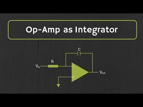
- The inverting configuration is explained, where a feedback capacitor replaces the feedback resistor, transforming the circuit into an integrator.
- Current flow is analyzed: Iin enters through a resistor R while Ic flows through the feedback capacitor Cf, establishing a virtual ground at the inverting input.
Applying Kirchhoff's Current Law (KCL)
- KCL is applied at the node to relate input current Iin and output current Ic flowing through capacitor Cf.
- The relationship between current and voltage across a capacitor is introduced: Ic = C * dVc/dt.
Deriving Output Voltage Expression
- By substituting expressions for currents into KCL, we derive that Vin/R = -Cf * d(Vout)/dt.
- Rearranging leads to d(Vout)/dt = [-1/(R*Cf)] * Vin; integrating both sides gives Vout as a function of Vin.
Understanding Integration Time Constant
- The output voltage expression indicates that Vout represents the integral of Vin over time, with R*Cf determining integration time.
- Practical examples are discussed: applying DC signals results in negative saturation output; sinusoidal inputs yield cosine outputs; square waves produce triangular waveforms.
Limitations of Simple Integrator Circuit
- Real-world applications may not yield expected outputs due to limitations inherent in simple integrator circuits.
- Gain analysis shows that at low frequencies (near zero Hertz), op-amp gain can be excessively high, leading to saturation issues.
Reactance and Frequency Considerations
- Capacitor reactance is defined as 1/(wC), affecting gain calculations. At DC levels, capacitors behave like open circuits causing potential saturation.
Understanding the Frequency Response of a Practical Integrator
Gain Characteristics of an Integrator
- The output voltage of a simple integrator decreases with frequency. At DC (0 Hz), the gain equals the open-loop gain of the op-amp, typically between 10^5 to 10^6 or 100 dB.
- As frequency increases, the gain reduces; thus, using an op-amp at higher frequencies can lead to distortion or saturation due to input offset voltage.
Input Offset Voltage Impact
- Real-world op-amps are not ideal and possess input offset voltages that can cause saturation even with small millivolt inputs. This offset gets integrated by the capacitor, pushing the output towards saturation.
- Introducing a feedback resistor in parallel with the capacitor helps mitigate saturation issues by reducing effective gain at low frequencies where the capacitor acts as an open circuit.
Feedback Resistor Functionality
- With a feedback resistor (R_f), at low frequencies, the gain seen by the op-amp is -R_f/R_1. This configuration allows for better handling of input offset voltages without saturating output.
- Practical integrators often include this feedback resistor alongside another resistor connected to the non-inverting terminal to counteract input bias currents, which will be discussed in further detail later.
Frequency Response Analysis
- The frequency response of practical integrators resembles that of low-pass filters; below a certain cut-off frequency (f_L), they maintain constant gain equal to -R_f/R_1. Above this frequency, output voltage begins to decrease significantly.
- Proper integration requires input signal frequencies above f_L and ideally ten times greater than this cut-off frequency for effective performance. The cut-off frequency is defined as f_L = 1/2 pi R_f C_f.
Examples and Calculations
Example 1: Cut-off Frequency Calculation
- Given values: C_f = 10 nF, R_f = 100 KΩ, and R = 1 KΩ; calculating cut-off frequency yields approximately 159 Hz.
- For proper integration, input signal frequencies must exceed this cut-off value and ideally be at least ten times greater (i.e., >1.59 kHz).
Example 2: Sinusoidal Input Signal Integration
- In a scenario where an input sinusoidal signal has a frequency of 5 kHz (well above our calculated cut-off), it will integrate effectively.
- The next step involves deriving expressions for output voltage based on these parameters and conditions established earlier in discussions about integrators' behavior under varying frequencies.
Integrator Circuit Analysis
Output Voltage Calculation from Sinusoidal Input
- The output voltage V_out after integrating a sinusoidal input signal is derived using the formula:
[
V_out = 10^5/2pi times 5000 cos(2pi times 5000t)
]
Simplifying this gives V_out = 3.18 cos(2pi times 5000t) .
Impact of Component Values on Output Amplitude
- The amplitude of the output voltage is influenced by the values of resistance R , capacitance C_f , and the frequency of the input signal.
Square Wave Input to Integrator Circuit
- When a square wave is applied to an integrator, the output will be a triangular wave. The time period for this square wave is noted as 100 microseconds.
Frequency Considerations in Integration
- The frequency of the square wave is calculated to be 10 kHz, which exceeds the cut-off frequency ( f_L = 159 Hz ) ensuring proper integration occurs.
Segment-wise Integration Approach
- To find the output voltage, divide the square wave into segments:
- From 0 to 50 microseconds, input signal = 2V.
- From 50 to 100 microseconds, input signal = -2V.
- For each segment, integrate separately:
- First segment yields an output swing from 5V to -5V with an integrated value of -10V.
- Second segment also results in a similar swing but in opposite direction.
Final Example and Exercise Prompt
- A new integrator circuit example is presented where an input signal lasts for 1 ms.
- The expected behavior includes maintaining output during no input (from 1 ms to 4 ms) and responding again when input resumes (from 4 ms to 5 ms).
- Viewers are encouraged to calculate and share their findings regarding this integrated output voltage.