Transformers -Amp-Turn Balance, Ideal and practical transformers
Discussion on Basic Transformer Operation
Overview of Transformer Components
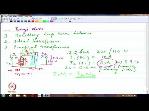
- The discussion begins with an explanation of the basic transformer structure, highlighting the ferromagnetic core, primary winding, and secondary winding.
- A voltage source (V1) is connected to the primary winding, resulting in a no-load current (I0), which establishes a magnetic flux in the core.
Current Calculations and Load Conditions
- For a 2.2 KVA transformer operating at 220V to 110V, the full load current on the primary side is calculated to be approximately 10A.
- When connecting a load of 5.5 Ω on the secondary side, it results in a secondary current (I2) of 20A.
Interaction Between Primary and Secondary Currents
- The established secondary current creates an opposing effect on the primary current due to Lenz's law, which states that induced currents oppose changes in magnetic flux.
- The relationship between turns ratio (N1 for primary and N2 for secondary windings) affects how these currents interact; if N1 has more turns than N2, it will dominate.
Effects of Induced EMF
- If there is any drop in induced EMF (e1), it can lead to significant increases in primary current due to reduced resistance from V1.
- In no-load conditions, even small fluctuations can cause substantial changes in EMF and subsequently affect overall transformer operation.
Balancing Ampere Turns
- The balance between I1N1 (primary ampere-turns) and I2N2 (secondary ampere-turns) ensures that mutual flux remains stable during operation.
- This balance is crucial for maintaining transformer functionality as it allows for efficient energy transfer between windings.
Ideal vs Practical Transformers
- Transitioning into ideal transformers, assumptions are made regarding zero resistance in windings and perfect conductors.
- These assumptions highlight differences when comparing ideal transformers with practical ones where losses occur due to resistance.
This structured summary captures key insights from the transcript while providing timestamps for easy reference.
Understanding Transformer Flux and Resistance
Establishing Core Assumptions
- The speaker discusses the necessity of zero current for establishing flux in a transformer, assuming infinite permeability of the core.
- It is emphasized that no current will be drawn to establish flow, maintaining that magnetizing current is zero.
- The absence of leakage is noted; all primary flux connects directly to the secondary, indicating no losses if resistance is negligible.
Power Relationships in Transformers
- The speaker asserts that input power equals output power under ideal conditions, with high efficiency (98% or 99%) expected due to minimal resistance.
- Introduction of load impedance (ZL) on the secondary side allows for analysis of power transfer as V2I2, assuming Z2 is purely resistive.
Impedance Transfer Between Primary and Secondary
- The discussion shifts to transferring load impedance from the secondary to the primary side for equivalent load representation.
- Visualizing how ZL represents actual impedance on the secondary side aids in understanding its impact on primary calculations.
Calculating Equivalent Load Impedance
- The speaker explains how to express relationships between voltages (V1 and V2), allowing for calculations based on I1 and I2 values.
- Emphasis is placed on representing load impedance accurately while considering winding ratios during transformations.
Practical Considerations in Transformer Design
- A practical approach involves recognizing challenges when transferring parameters from one side of a transformer to another.
- The speaker illustrates a basic circuit setup with windings and loads, simplifying complex representations into manageable components.
Addressing Real-world Transformer Limitations
- Discussion includes neglecting magnetic coupling losses while focusing on primary and secondary resistances (R1 and R2).
- Acknowledgment of electromagnetic lines flowing through cores highlights potential leakage paths affecting performance.
Conclusion: Understanding Leakage Flux Lines
- The importance of recognizing leakage flux lines in transformers is reiterated; they can affect overall efficiency by diverting some magnetic lines away from intended paths.
Understanding Leakage and Reactance in Electrical Circuits
The Nature of Leakage
- Leakage occurs primarily through air pathways, not through iron components. This suggests that the flow of current can be influenced by secondary connections without direct contact.
- Self-induced EMF (Electromotive Force) is a critical factor in leakage, as it leads to voltage drops that represent lost energy within the circuit.
Representation of Inductance and Reactance
- Leakage reactance is identified as a significant parameter, with specific inductances associated with primary (Ll1) and secondary (Ll2) circuits.
- The representation of leakage can be expressed through inductive drops, which are essential for understanding how energy loss manifests in electrical systems.
Magnetic Reluctance and Circuit Behavior
- Reluctance paths are crucial when considering magnetic characteristics; they remain stable unless external factors change the magnetic properties of the core material.
- The reluctance associated with air gaps is treated as constant, allowing for predictable behavior in circuit analysis.
Voltage Relationships in Transformers
- Ll1 and Ll2 do not necessarily equate; their relationship depends on transformer design rather than being inherently similar or stable.
- When applying voltage V1 across coils Ll1 and Ll2, the current I1 must correlate directly to winding ratios, affecting overall circuit performance.
Analyzing Voltage Drops
- The induced EMF (e1), which relates to primary coil voltage V1, will always be less than V1 due to inherent losses from resistance and reactance.
- Terminal voltages (VLoad and V2), after accounting for various drops across resistances, illustrate how real-world applications differ from theoretical models.
Losses Due to Resistance
- Two distinct voltage drops occur: one from primary resistance related to leakage reactance and another from secondary resistance. These contribute significantly to total energy loss.
- Even minimal resistances can have substantial impacts on performance when dealing with high currents; thus, they should not be overlooked during calculations.
Hysteresis Losses in Magnetic Cores
- Hysteresis losses arise during magnetization cycles even under no-load conditions. These need careful consideration when analyzing efficiency.
- Mutual flux established between coils influences self-induced EMF but does not align perfectly due to differences in core materials' properties.
Implications for Circuit Design
- Understanding these principles allows engineers to better design circuits that minimize losses while maximizing efficiency through careful selection of materials and configurations.
Magnetizing Current and Inductance in Transformers
Understanding Magnetizing Current
- The magnetizing current is the initial flow that establishes magnetic flux, which is crucial for transformer operation. It is not dependent on I1 or I2 until it enters the circuit.
- Discusses the difficulty of defining a stable operating point without specifying conditions under which the transformer operates, emphasizing the importance of these parameters.
Magnetic Characteristics and Hysteresis Loop
- The speaker highlights that inductance values vary at different points within the hysteresis loop, indicating that operational characteristics are not uniform across all scenarios.
- Mutual flux connects primary and secondary windings but remains confined to the core, preventing leakage and ensuring efficient magnetic field establishment.
Transformer Operation Points
- The established current (Im) is critical for generating induced voltage (V2), with I1 protecting against potential overload from I2.
- Emphasizes that mutual flux depends on specific operating points; variations in inductance (Lm) occur when examining different operational conditions.
Flux Establishment and Reactance
- Once set at a specific operating point, both current and flux remain constant unless external conditions change significantly.
- Introduces sinusoidal excitation as a method to represent induction through varying currents, leading to discussions about magnetizing reactance (Xm).
Equivalent Circuit Representation
- Refers back to earlier discussions on equivalent circuits for ferromagnetic cores, where resistance represents main currents while inductance signifies those used for establishing flux.
- Describes how no-load current consists of two components: one representing real power loss and another as reactive power due to inductive effects.
Voltage Ratings and Operating Conditions
- Clarifies that nominal voltage correlates directly with fixed flux values; thus, if nominal flux is established, magnetizing current becomes predictable based on defined operating points.
- Notes that plotting Lm against various voltages will show stability only at rated conditions; deviations lead to changes in operational characteristics.
This structured summary captures key insights from the transcript regarding transformers' magnetization processes, their operational characteristics under varying conditions, and how these factors influence overall performance.
Secondary Winding Leakage Reactance and Transformer Analysis
Understanding Secondary Winding Leakage Reactance
- The speaker introduces the concept of secondary winding leakage reactance (X2) in transformers, emphasizing its representation through a ferromagnetic core equivalent circuit.
- A distinction is made between ideal primary and secondary windings, highlighting the non-ideal characteristics of transformers due to resistance and inductance.
- The discussion includes transferring parameters from the primary side to the secondary side, noting that excitation typically comes from the primary side while loads are connected to the secondary.
Losses in Transformers
- The speaker mentions hysteresis loss quantified at 2.2 kW, comparing it with a hypothetical 100 watts for better understanding.
- It is explained that there are resistive and inductive currents within transformers; these currents contribute differently to overall losses.
- The no-load current (I0) consists of two components: one related to magnetizing flow and another associated with core losses.
Phasor Diagrams and Load Conditions
- A phasor diagram representing no-load conditions is introduced, illustrating how load connections affect transformer operation.
- The relationship between reflected current (I2), no-load current (I0), and total current (I1) is discussed, indicating I0 can often be neglected for simplicity unless precision is required.
Core Loss Components
- Core loss components are analyzed further; it’s noted that laminated cores significantly reduce eddy current losses while hysteresis losses persist.