Архитектура ЭВМ. Лекция 2: АЛУ. Устройство памяти
Speed of Logic Circuits
The speed at which different logic circuits switch depends on the number of elements in the circuit. The time it takes for a signal to propagate through the circuit affects how quickly it can be processed.
Factors Affecting Switching Speed
- The speed of switching between different logic circuits varies based on the number of elements present.
- The time taken for signal transmission determines how long it takes for a specific operation to complete.
- Different logical elements, such as AND, OR, or others, have varying switching speeds.
Synchronization Signals and Clock Generators
To control and synchronize computational systems effectively, synchronization signals are used. These signals ensure that logic circuits switch at specific moments and remain stable when needed.
Importance of Synchronization Signals
- Synchronization signals are essential for controlling and managing computational systems.
- All elements in a system that involve memory have a synchronizing signal input.
- A synchronizing pulse ensures that all components switch simultaneously and maintain stability.
Introduction to Clock Generators
Clock generators play a crucial role in computer systems by providing synchronized timing pulses. These pulses enable precise control over the switching behavior of logic circuits.
Purpose of Clock Generators
- Clock generators produce timing pulses required for controlling computational systems.
- They ensure that logic circuits switch at specific intervals or moments.
- Clock generators are necessary for accurate computation and data processing.
Multiplexers
Multiplexers are versatile components used in various applications. Understanding their structure and functionality is important for effective utilization in computing systems
How to Create a Half Adder
In this section, the speaker explains how to create a half adder using logic gates. The process is demonstrated through diagrams and logical explanations.
Creating a Half Adder
- A half adder can be created by drawing a diagram of logical elements in the form of squares.
- Two input bits, labeled as "a" and "b," are sequentially added together.
- The sum of the inputs is obtained by adding the bits "a" and "b."
- The carry bit is obtained by adding the carry from the previous operation with the result.
- This process results in a half adder that can add two bits with consideration for carry.
Representation of Multi-Bit Numbers
The speaker discusses different ways to represent multi-bit numbers and how they are denoted in diagrams.
Representation of Multi-Bit Numbers
- Multi-bit numbers can be represented using horizontal lines called buses, with numbers written next to them indicating their size.
- Specific bits within a bus can be denoted by listing their positions or using dots to represent ranges.
- For example, if specific bits 3, 5, and 12 are used from a bus, they can be represented as "3, 5..8" or "3, 5...8."
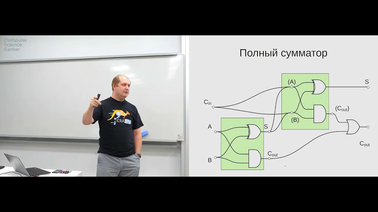
Full Adders and Overflow
The speaker introduces full adders and discusses overflow in computational systems.
Full Adders and Overflow
- Thirty-two full adders can be combined sequentially to create a 32-bit adder.
- However, there is an issue with this approach due to potential overflow when working with large numbers or slow switching speeds.
- Overflow occurs when the result of an addition exceeds the capacity of the computational system.
- Overflow can be managed
Understanding Carry Propagation and Generation in Binary Addition
In this section, the speaker explains the concepts of carry propagation and generation in binary addition. They discuss how these signals are used to determine if a carry is generated or propagated during addition.
Carry Generation and Propagation Signals
- The speaker introduces two sets of signals: "generation" and "propagation."
- The "generation" signal indicates when a carry is generated between specific bits in the addition.
- The "propagation" signal indicates when a carry from a lower bit is propagated to a higher bit.
Determining Carry Generation
- The generation signal represents the specific bits where a carry is generated during addition.
- When examining the binary addition process, the generation signal is present at certain bits.
- By analyzing the input signals, it is possible to determine if a carry will be generated or not.
Understanding Carry Propagation
- Carry propagation refers to the transmission of carries from lower-order bits to higher-order bits.
- If there is a carry from the least significant bit (LSB), it will be propagated to subsequent bits.
- The presence or absence of carries affects how numbers are added together.
Simplifying Binary Addition with Carry Propagation and Generation
- By utilizing carry propagation and generation signals, it becomes easier to perform binary addition.
- These signals allow for separate calculations of operands, making them faster than combined operations.
- Combining these techniques can significantly reduce computation time.
Extrapolating for Larger Numbers
- The speaker discusses extrapolating these concepts for larger numbers, such as 32-bit additions.
- They explain that by dividing the calculation into smaller sections, each section can be processed independently before combining them at later stages.
Benefits of Carry Propagation and Generation in Binary Addition
In this section, the speaker highlights the advantages of using carry propagation and generation signals in binary addition. They discuss how these techniques can reduce computation time and improve efficiency.
Reducing Computation Time
- The
Simplifying the Process
The speaker suggests simplifying the process by grouping calculations into larger blocks. They discuss the desire for each block to have a consistent time duration for accurate results.
Simplification and Optimization
- The speaker proposes simplifying the process by grouping calculations into larger blocks.
- The goal is to have a consistent time duration for each block to ensure accurate results.
- The number of elements in each block can be adjusted based on optimization requirements.
Constraints and Considerations
- There are certain constraints and considerations when optimizing the process.
- The desired outcome is to minimize delays between calculations while maintaining accuracy.
- Creating a complex scheme that performs immediate transfers may result in higher costs.
Example with 16 Elements
- An example is given where a more complex scheme is created for 16 elements.
- This demonstrates how increasing complexity can impact cost and efficiency.
Using Additional Code for Subtraction
The speaker discusses using additional code, such as two's complement, to perform subtraction in binary systems.
Two's Complement Method
- To perform subtraction in binary systems, the two's complement method can be used.
- This involves inverting all bits of the number being subtracted and adding 1 to it.
Benefits of Two's Complement
- Two's complement allows for easy representation of negative numbers in binary systems.
- It simplifies subtraction operations by converting them into addition operations with inverted numbers.
Binary Arithmetic and Limitations
The speaker explains binary arithmetic and its limitations, particularly regarding the number of bits available in computer systems.
Binary Representation of Numbers
- In binary representation, numbers are expressed using only 0s and 1s.
- A specific number of bits determines the range of values that can be represented.
Limitations of Bit Count
- The number of bits available in a computer system limits the range of values that can be represented.
- For
Understanding the Comparator Block
In this section, the speaker discusses the concept of a comparator block and its purpose in comparing two 8-bit numbers.
Implementing a Comparator Block
- A comparator block is used to compare two 8-bit numbers, denoted as 'a' and 'b'.
- The desired output signals from the comparator block include:
- Equality signal (1 if 'a' equals 'b', 0 otherwise)
- Less than signal (1 if 'a' is less than 'b', 0 otherwise)
- Greater than signal (1 if 'a' is greater than 'b', 0 otherwise)
Understanding Assembly Commands
- The speaker explains various assembly commands used in implementing the comparator block.
- These commands include:
- Not equal
- Equal
- Less or equal
- Greater or equal
- These commands are essential for performing comparisons in assembly language.
Implementing Comparison Logic
- The speaker discusses how to implement comparison logic using existing basic elements such as AND, OR, NOT gates, and a full adder.
- By subtracting 'b' from 'a', it is possible to determine whether 'a' is greater or less than 'b'.
- The most significant bit of the subtraction result indicates whether the numbers are positive or negative.
Arithmetic Logic Unit (ALU)
- The ALU combines arithmetic and logical operations.
- It performs addition, subtraction, and other operations simultaneously based on control signals.
- A multiplexer selects the appropriate operation based on input control signals.
Summary of ALU Operations
- The ALU can perform various operations such as addition, subtraction, multiplication, division, etc.
- Control signals determine which operation to perform.
Introduction to Counters
In this section, the speaker introduces counters and their significance in computer systems.
How the Command Counter Works
This section explains how the command counter works and its role in executing commands.
The Command Counter
- The command counter keeps track of the number of commands executed.
- It indicates the current command number and helps in reading, executing, and storing results.
- The counter is a register that stores a binary number representing the command's position.
Register and its Functionality
- A register is a collection of memory bits that store binary numbers.
- It holds numbers of a specific bit size, known as the register's word length.
- In this case, the register is an n-bit register, where n represents its word length.
Impulse Generation and Incrementing
- One part of the register generates an impulse signal.
- Another part increments the stored value by one after each command execution.
Multiplying Counter with Command Length
- The counter can be multiplied by the length of each command to determine memory addresses for subsequent commands.
- This allows flexibility in handling commands with varying lengths.
Understanding Memory Structure
This section discusses how memory is structured and how it relates to address buses and data buses.
Memory Array
- Memory consists of an array that stores elements or bits.
- Each element can hold multiple bits based on its word length.
Address Bus and Data Bus
- There are two address buses: A1 (for lower-order bits) and A2 (for higher-order bits).
- These buses are used to specify memory addresses for reading or writing data.
Writing Data to Memory
- To write data to memory, an address along with data is provided on both address buses and data bus respectively.
Clock Signal for Writing Data
- Writing data occurs when a clock signal arrives.
Decoders and Memory Selection
This section explains the role of decoders in memory selection and how they enable accessing specific memory locations.
Decoders
- Decoders convert binary numbers into specific output lines.
- They are used to select a particular set of triggers that store bits of a word.
Artline and Beltline
- The artline is a decoder that selects the triggers holding bits for a specific word.
- It ensures that only one trigger is active, while others remain inactive.
Addressing Memory and Word Size
This section discusses how memory addressing works and the relationship between address bus width and word size.
Memory Addressing
- Memory addressing involves specifying an address to access data stored in memory.
- The address determines which triggers hold the bits for a particular word.
Address Bus Width vs. Word Size
- The number of bits in the address bus
Memory Types and Architecture
In this section, the speaker discusses different types of memory and their architecture.
Dynamic and Static Memory
- Dynamic memory stores data using capacitors that hold charge to represent 1 or 0.
- Dynamic memory requires constant refreshing due to charge leakage.
- Static memory uses flip-flops and does not require refreshing.
- Static memory is faster but more expensive than dynamic memory.
Cache Memory
- Cache memory is implemented as flip-flops on the same chip as the processor.
- Cache memory improves performance by storing frequently accessed data closer to the processor.
RAM and Storage Devices
- RAM (Random Access Memory) is separate from the processor and comes in different types such as SRAM (Static RAM).
- Multiple channels in RAM allow for faster data transfer.
- Hard disk drives (HDD) use mechanical components, while solid-state drives (SSD) use static memory.
- SSD can be 3D, with movable molecules for higher capacity.
The transcript contains additional information about specific storage devices that can be explored further.