PROTOCOLOS: UART - I2C - SPI - Comunicación Serie #001
What is Serial Communication?
Introduction to Serial Communication
- Serial communication is a method for transmitting digital data using fewer connections, with various protocols available, particularly popular ones for basic microcontrollers like Pico and Arduino.
- The video will cover the concept of serial communication, focusing on three main examples: UART, I2C, and SPI. It will explain their characteristics and provide practical examples using Arduino.
Importance of Oscilloscope in Understanding Signals
- An oscilloscope will be used to visualize signals, enhancing understanding of how these protocols function.
Understanding Protocols and Their Characteristics
Overview of PCB Manufacturing Services
- The episode is sponsored by a PCB manufacturing company offering services such as two-layer PCBs for $2 and assembly processes where components are pre-soldered.
Definition of Serial Communication Protocol
- A serial communication protocol transmits data sequentially (one after another), which contrasts with parallel communication that sends multiple bits simultaneously.
Advantages and Disadvantages of Parallel vs. Serial Communication
- In parallel communication, sending 8 bits requires 9 wires (8 data + ground), while serial only needs one wire but can be slower due to needing multiple clock pulses.
- Sending 16 bits in parallel requires one pulse; in contrast, serial transmission would need 16 clock pulses, making it significantly slower.
Types of Serial Communication
Synchronous vs. Asynchronous Communication
- Serial communications can be synchronous (using a clock signal) or asynchronous (without a clock). The key difference lies in how they manage timing for data transmission.
Introduction to UART Protocol
- UART (Universal Asynchronous Receiver/Transmitter) uses one wire for data transmission plus ground. It relies on common settings between transmitter and receiver before establishing connections.
Key Configuration Settings for UART
- Essential configurations include baud rate (transmission speed), data length in bits, start bit type, and stop bit type. These must match on both ends for successful communication.
Data Transmission Process Using UART
Example Data Transmission
- To send the number 198 as binary through UART involves sending 8 bits along with additional start and stop bits to frame the message correctly.
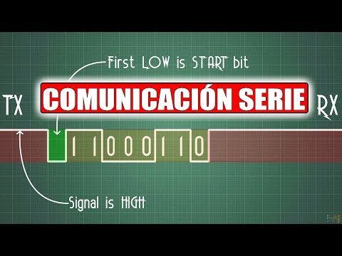
Signal Representation in UART
- The typical idle state is high; the start bit is low. This allows the receiver to detect when data begins based on changes from high to low signals.
Timing Considerations
Communication Protocols Overview
Ward Communication Basics
- The start and stop bits in ward communication are consistently structured, forming the basis of how this communication operates.
- RS232 is highlighted as an older communication method used in computers, with Arduino utilizing it for code uploads and serial monitor data transmission.
- A ward chip includes pins like TR (transmit ready) and CTS (clear to send), which help manage data flow readiness between devices.
I2C Communication Protocol
- The I2C protocol, developed by Philips, requires two additional connections: ground reference and a clock line (SCL).
- Data transmission involves sending 15 or 16 bits simultaneously while generating a clock signal at the same frequency to synchronize bit timing.
- Each receiver has a unique slave address; the transmitter sends this address before transmitting data, ensuring only the intended recipient processes it.
SPI Communication Protocol
- SPI (Serial Peripheral Interface) adds complexity with three additional lines: MOSI (Master Out Slave In), MISO (Master In Slave Out), and Chip Select alongside SCL.
- This protocol allows full-duplex communication where both master and slave can transmit simultaneously, unlike I2C's half-duplex nature.
- SPI supports higher transmission speeds than I2C but lacks long-distance capabilities seen in RS232 due to its design limitations.
Practical Applications & Considerations
- While SPI offers faster speeds and lower power consumption compared to I2C, it requires more wiring for multiple slaves due to individual chip select lines.
- Unlike RS232's handshaking signals (RTS/CTS), SPI does not have built-in acknowledgment mechanisms for connected devices.