Fatigue, dureté, usure
Introduction to Fatigue, Hardness, and Wear in Materials
In this chapter, we will discuss three aspects related to the properties of materials: fatigue, hardness, and wear. We will start with an introduction to fatigue.
Fatigue
- Fatigue refers to the phenomenon where a material fails after being subjected to repeated loading and unloading cycles.
- It can occur even when the stress applied is below the yield strength of the material.
- Examples of fatigue include bending a trombone repeatedly until it breaks or the vibrations produced by a bell or Tibetan bowl.
- Fatigue can lead to crack initiation and propagation in materials over time.
Hardness
- Hardness is a measure of a material's resistance to indentation or scratching.
- It determines how well a material can withstand wear and deformation.
- Different tests are used to measure hardness, such as the Rockwell hardness test or Brinell hardness test.
Wear
- Wear refers to the gradual loss of material due to contact with another surface during relative motion.
- It can be caused by factors like friction, abrasion, adhesion, or erosion.
- Wear resistance is an important property for materials used in applications where they come into contact with other surfaces.
Types of Fatigue
There are different types of fatigue that materials can experience. This section explores two extremes: low-cycle fatigue and high-cycle vibration.
Low-Cycle Fatigue
- Low-cycle fatigue occurs when a material undergoes failure after a small number of loading cycles under high stress levels.
- This type of fatigue is characterized by rapid crack growth and failure within a few cycles.
High-Cycle Vibration
- High-cycle vibration refers to the phenomenon where materials experience cyclic stresses due to vibrations over an extended period.
- Examples include bells or Tibetan bowls vibrating after being struck.
- Materials with good vibration characteristics can sustain vibrations for a long time without significant attenuation.
Fatigue Testing
Fatigue testing involves applying cyclic stresses to a material and observing when it fails. This section discusses the process and challenges of fatigue testing.
Fatigue Test Setup
- Fatigue tests typically involve subjecting a material to cyclic loading, often using a machine that applies periodic stress.
- The number of cycles required for failure is determined by the applied stress level and other factors.
- These tests can be expensive and time-consuming, especially for high-stress levels that require a large number of cycles.
Example: Fatigue Test on a Rod
- A simple fatigue test setup involves suspending a rod with one end fixed and attaching weights to the other end.
- The rod undergoes cyclic loading as it rotates, experiencing tension or compression depending on its position.
- By monitoring the number of cycles before failure, we can assess the fatigue behavior of the material.
Indirect Fatigue Testing
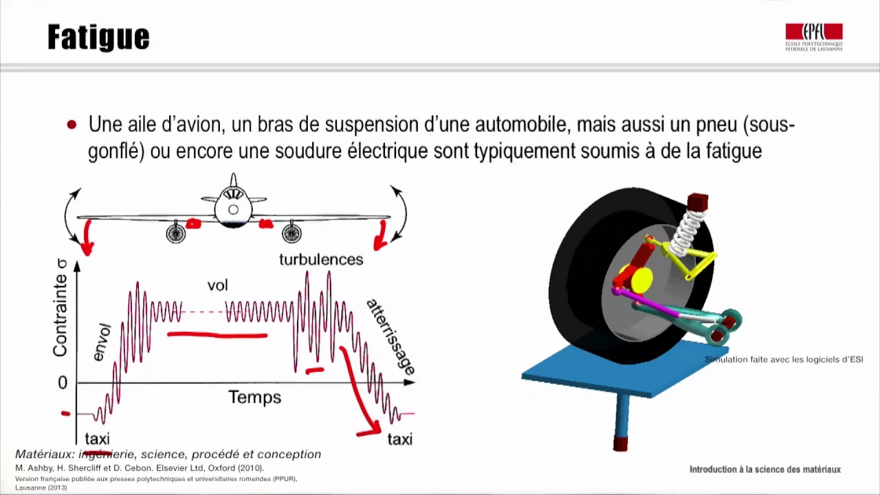
Some devices indirectly experience fatigue through various operational conditions. This section explores an example related to aircraft wings.
Aircraft Wing Example
- Aircraft wings are subjected to varying loads during different phases of flight, including taxiing, takeoff, cruising, turbulence, and landing.
- To study the effects of these loads on wing fatigue, sensors can be placed underneath the wings to measure strain variations.
- This indirect testing helps understand how different operational conditions contribute to wing fatigue.
Conclusion
In this chapter, we explored the concepts of fatigue, hardness, and wear in materials. We discussed different types of fatigue and examined examples such as low-cycle fatigue and high-cycle vibration. Additionally, we learned about the process of fatigue testing using both direct and indirect methods. Understanding these aspects is crucial for designing materials that can withstand repeated loading and ensure their longevity in various applications.
Aluminum Manufacturer and Fatigue Testing
This section discusses the concept of fatigue in materials, specifically focusing on aluminum manufacturing and fatigue testing.
Aluminum Manufacturing and Fatigue
- Aluminum manufacturers state that only about 10% of aluminum is used for flying, while the remaining 90% is used for other purposes.
- Suspension arms in cars are an important example of components that provide comfort by minimizing vibrations from the road to the vehicle's cabin.
- Suspension arms are subjected to fatigue due to various factors such as road conditions and accidents.
- Most suspension arms are made through forging rather than casting alloys because forging provides better resistance to fatigue.
Understanding Fatigue
- Before discussing fatigue, some definitions need to be clarified.
- Tensile tests help understand material behavior under tension. The yield strength (σ02) represents the point where plastic deformation begins, while ultimate tensile strength (σm) indicates the maximum stress a material can withstand before breaking.
- Fatigue can be categorized into different types based on stress levels: normal fatigue occurs when stress remains within elastic limits, oligo-cyclic fatigue occurs between elastic limits and ultimate tensile strength, and high-cycle or low-cycle fatigue occurs at higher stress levels.
Fatigue Testing
- Fatigue testing involves applying cyclic loading to a material specimen until it fails.
- Tests are often conducted with zero mean stress (average stress equals zero).
- The number of cycles required for failure is plotted against the applied stress amplitude on a logarithmic scale.
- Higher amplitudes lead to faster failure, especially in oligo-cyclic fatigue regimes.
Practical Aspects of Fatigue Testing
This section explores practical aspects of conducting fatigue tests and how different factors affect the results.
Conducting a Fatigue Test
- A typical test involves applying cyclic loading to a specimen with a small crack or notch.
- The test is often performed with zero mean stress, meaning the average stress is zero.
- The applied stress consists of an amplitude and a mean value.
Factors Affecting Fatigue Testing
- The number of cycles to failure increases as the applied stress decreases.
- Higher amplitudes lead to faster failure in fatigue tests.
- In low-cycle fatigue, failure can occur after a relatively small number of cycles, while high-cycle fatigue involves a larger number of cycles before failure.
Understanding Fatigue Curves
- Fatigue curves are plotted by connecting points representing the number of cycles to failure for different stress amplitudes.
- These curves help understand the relationship between stress amplitude and fatigue life.
Practical Applications and Conclusion
This section discusses practical applications of fatigue testing and concludes the discussion on fatigue in materials.
Practical Applications
- Fatigue testing helps determine the durability and reliability of materials under cyclic loading conditions.
- It is crucial for industries such as automotive, aerospace, and structural engineering to ensure safe designs and prevent unexpected failures due to fatigue.
Conclusion
- Fatigue is an important consideration in material design and manufacturing processes.
- Understanding how materials behave under cyclic loading conditions helps engineers make informed decisions about component design and material selection.
[t=0:16:34s] Courbe optimale passante et à tous ces un donc du bronze très peu d'atténuation parce que en fait coups de marteau sa section et très peu marteau et bien on ferme tous les petits formés lors de la préparation de cet vibration très bonne sonorité casting par exemple pour dire que c'est de porosité donc ici on a un exemple
This section discusses the optimal passing curve and the properties of bronze, including its low attenuation and good sound quality. The example of casting is used to illustrate the concept of porosity.
Bronze Properties
- Bronze has very little attenuation and produces a good sound quality.
- When hammered, its section remains intact with minimal deformation.
- Casting bronze can exhibit porosity, which affects its properties.
[t=0:02:49s] D'une variation quand même de cours du temps un test de fatigue souvent périodiques et à regarder quand qui sont très coûteux parce qu'ils contrainte appliquée mais allant voir la salle d'expérience les uns ce très les à un test de fatigue consiste à constante dans le temps sont soumis à des tests de fatigue on
This section introduces the concept of fatigue testing, which involves subjecting materials to constant cyclic loading over time. Fatigue tests can be expensive due to the applied stress levels.
Fatigue Testing
- Fatigue testing involves subjecting materials to constant cyclic loading over time.
- These tests are costly due to the high levels of applied stress.
[t=0:03:36s] Suspension d'un véhicule ya toutes les l'intel de fatigue en général réalisé mettre les champions comme on l'a fait appliquer une contrainte de traction une tractions une compression cours du temps faudra faire avant qu'il y ait rupture amplitude deux contre un qui est exemple au maximum 50 mégas pascal en
This section discusses fatigue in vehicle suspensions and the application of tension and compression forces over time. The example of a maximum stress level of 50 megapascals is mentioned.
Vehicle Suspension Fatigue
- Vehicle suspensions undergo fatigue due to the application of tension and compression forces over time.
- Before failure occurs, it is necessary to determine the maximum stress levels, such as 50 megapascals.
[t=0:04:11s] Parce qu'alain compression telle manière alors on l'a on va pas dit la machine compliquer alors on va utiliser plus simple donc en fait c'est une sorte on a une rotation simplement d'un côté qu'on va tester de l'autre côté on va la soumettre à traction compression intelligent en aluminium et où on a fait
This section explains a simplified method for testing materials under tension and compression using rotational motion. An example involving intelligent aluminum is mentioned.
Simplified Testing Method
- A simplified testing method involves rotating the material to be tested on one side while subjecting it to tension or compression on the other side.
- An example using intelligent aluminum is provided.
[t=0:04:56s] Rival à voir et en fait on en suspendre taille donc côte quand il est tourné lorsqu'il sera tourné dans l'autre sens grâce à la rotation ça va faire traction c'est un test relativement sain donc si environ un kilo je mets tout au bout il telle manière pouvoir laisser la la barre qui montre bien qu'on est
This section describes how rotational motion can be used to apply traction during testing. The concept of leaving a bar suspended at the end is mentioned.
Traction Testing with Rotation
- By rotating the material, traction can be applied in one direction.
- Suspending a bar at the end allows for observation of its behavior under tension.
[t=0:05:40s] Évidemment il ya des efforts de traction
This section briefly mentions the presence of traction forces.
Traction Forces
- Traction forces are present during testing.
[t=0:05:48s] Voilà la rotation traction compression test faire et regardons combien temps ça
This section introduces the concept of rotation traction compression testing and mentions the need to observe its duration.
Rotation Traction Compression Test
- The rotation traction compression test is performed to observe its duration.
[t=0:06:08s] Comme on peut le voir après un certain quand bien même elle supporter en quelque part la surface de rupture du pour la fatigue justement parce que ça progressivement tout à fait bien de théorie
This section discusses the observation of rupture surfaces and their relation to fatigue. The importance of theoretical understanding is emphasized.
Rupture Surfaces and Fatigue
- Rupture surfaces can be observed after a certain period, indicating fatigue.
- A good theoretical understanding is crucial in studying fatigue.
[t=0:06:42s] Dispositifs qui sont soumis à des tests tests qui vont être soumis à de la un exemple d'une aile d'avion qui va capteur sous les ailes par exemple ici pourquoi dessous parce que lorsque et cage be lorsque l'on est au sol c'est à avec les roues qui pose par terre et amener l'ale plutôt vers le bas comme
This section discusses devices that undergo testing, using the example of an airplane wing with sensors placed underneath. The behavior of the wing during different conditions is mentioned.
Testing Devices
- Various devices undergo testing, such as airplane wings.
- Sensors can be placed underneath the wings to monitor their behavior during different conditions.
[t=0:07:30s] Inférieure de l'est les plus tôt en ici et puis ils roulent ils transforment envoi il ya bien sûr des vibrations certain temps ils purent des turbulences à la procédure inverse comme on tient à ce que les ailes l'avion il faut éviter qui bien sûr une structure interne de l'oeil d'avion et usinage raison pour laquelle souvent lé
This section explains the importance of avoiding vibrations and turbulence in aircraft wings due to their internal structure and machining process.
Avoiding Vibrations and Turbulence in Aircraft Wings
- Vibrations and turbulence should be avoided in aircraft wings due to their internal structure and machining process.
[t=0:08:20s] Qu' environ que 10% qui volent et 90 % un autre exemple très important que l'on film droite c'est un bras de suspension de dénivelés les petits accidents les assure un certain confort à l'intérieur assurer le fait de la transmis de la non route sur l'habitacle de la voiture qui soumis à de pas mal de fatigue
This section discusses the importance of suspension arms in vehicles for comfort and transmitting road forces. It mentions that these components are subjected to significant fatigue.
Suspension Arms in Vehicles
Tracer
This section discusses the formation of defects in materials and their impact on fatigue. It also mentions the preference for forged parts over cast parts to minimize defects.
Defects in Plastic Deformation
- During plastic deformation, various defects such as tears and micro-cracks form in the material.
- These defects can lead to larger damages and micro-tears when the material is closed again.
- The presence of these defects increases the likelihood of cracking, especially in highly stressed components subjected to fatigue.
Forged Parts vs Cast Parts
- For highly stressed components prone to fatigue, forged parts are preferred over cast parts.
- Forged parts have fewer internal defects compared to cast parts, which often suffer from porosity.
Plus Vouloir Se Déformer
This section explains how stress amplitudes are adjusted based on mean stress values using Goodman's relation.
Adjusting Stress Amplitudes with Mean Stress
- Goodman proposed a simple relation for adjusting stress amplitudes based on mean stress values.
- When the mean stress value is not zero (σm ≠ 0), the amplitude is reduced by a factor of (1 - σm/σmax).
- This reduction factor depends on whether the material is predominantly under tension or compression.
Domaine Plastique et Défauts
This section discusses the formation of defects during plastic deformation and their role in crack initiation.
Defect Formation in Plastic Deformation
- In the plastic deformation range, various types of defects form within the material, such as micro-cracks and tearings.
- These defects contribute to crack initiation and propagation during cyclic loading.
- Cast parts are more prone to defects, such as porosity, compared to forged parts.
Pièces Très Sollicitées en Fatigue
This section explains the preference for forged parts in highly stressed components subjected to fatigue.
Forged Parts for Fatigue Applications
- For highly stressed components subjected to fatigue, such as car suspensions, forged parts are preferred.
- Forged parts have fewer defects compared to cast parts, resulting in improved fatigue performance.
Adaptation de la Courbe de Wöhler
This section discusses the adaptation of the Wöhler curve when mean stress is not zero.
Adapting the Wöhler Curve
- Adapting the Wöhler curve for non-zero mean stress values would require extensive and costly testing.
- Instead of conducting new tests, an elastic approach is used to adjust the curve based on measured data.
- The adjustment factor (1 - σm/σmax) is used to justify why higher mean stress values result in reduced stress amplitudes.
Relation de Goodman
This section introduces Goodman's relation for adjusting stress amplitudes with non-zero mean stress values.
Goodman's Relation
- Goodman proposed a simple relation stating that if σm ≠ 0, then the amplitude should be reduced by a factor of (1 - σm/σmax).
- The reduction factor depends on whether the material is predominantly under tension or compression.
- A positive reduction factor indicates a predominance of tensile stresses, while a negative reduction factor indicates a predominance of compressive stresses.
Réduction des Amplitudes avec Sigma Moyen
This section explains how the reduction factor in Goodman's relation affects stress amplitudes.
Reduction of Stress Amplitudes
- The reduction factor (1 - σm/σmax) determines the decrease in stress amplitude due to non-zero mean stress.
- If σm = σmax, then the amplitude becomes zero, indicating that no additional cyclic loading can be applied.
- By extrapolating this concept, different reduction factors can be determined for various mean stress values.
Courbes de Wöhler Adaptées
This section discusses the adaptation of Wöhler curves for different mean stress values.
Adaptation of Wöhler Curves
- Wöhler curves can be adapted based on different mean stress values.
- As the mean stress value increases, the curves gradually shift towards zero.
- The reduction factor (1 - σm/σmax) is used to adjust and plot these adapted curves.
Augmentation de Sigma Moyen
This section explains how increasing mean stress affects the adaptation of Wöhler curves.
Increasing Mean Stress
- As the mean stress value increases, the adapted Wöhler curves progressively shift towards zero.
- The reduction factor (1 - σm/σmax) plays a crucial role in determining these shifts.
- Higher positive mean stress values result in a greater decrease in stress amplitudes.
Cas d'Amplitude de Contraintes Variable
This section discusses adapting Wöhler curves when there are variations in stress amplitude over time.
Adapting to Variable Stress Amplitude
- In cases where there are variations in stress amplitude over time, such as in aircraft applications, the adaptation of Wöhler curves becomes more complex.
- For simplicity, this section assumes a constant mean stress value (σm = 0) and focuses on the number of cycles applied at different stress amplitudes.
Critère de Rupture
This section explains the criterion for rupture based on the accumulated damage.
Criterion for Rupture
- Rupture occurs when the accumulated damage reaches a critical value.
- The accumulated damage is determined by dividing the effective number of cycles by the number of cycles required to cause rupture at a specific stress amplitude.
- When the sum of these ratios equals 1, rupture occurs.
The transcript provided is in French.
Les propriétés élastiques des matériaux
Cette section aborde les propriétés élastiques des matériaux, en mettant l'accent sur le retour élastique dans les procédés de forgeage.
Retour élastique dans les procédés de forgeage
- Le retour élastique est un phénomène important à prendre en compte lors du forgeage de pièces.
- Lorsque la pression est appliquée pour former une pièce, il y a un retour élastique qui peut affecter la forme finale.
- Les ingénieurs doivent tenir compte du retour élastique pour calculer la forme du moule afin d'obtenir la bonne forme après avoir retiré la pièce de la forge.
L'usure des matériaux
Cette section traite de l'usure des matériaux et de son impact sur leur durabilité.
Mécanismes d'usure
- L'usure est un mécanisme courant qui entraîne la dégradation des matériaux au fil du temps.
- Lorsqu'un matériau frotte contre un autre, il peut perdre de la masse et se détériorer progressivement.
- L'usure peut être causée par le frottement et la corrosion, ce qui nécessite souvent le remplacement fréquent de certaines pièces.
Mesure de l'usure
- Pour mesurer l'usure d'un matériau, on utilise souvent une méthode consistant à faire tourner un disque en contact avec un pion fixe.
- Après un certain temps, on mesure la perte de masse du pion pour déterminer le taux d'usure.
- Les tests d'usure peuvent également être effectués en utilisant des disques de polissage avec des particules abrasives pour simuler l'usure réelle.
Effets du polissage
- Le polissage mécanique est un processus qui vise à améliorer la finition de surface d'un matériau.
- Différents papiers abrasifs sont utilisés, allant des plus grossiers aux plus fins, pour obtenir différentes granulométries de surface.
- Le polissage peut réduire les aspérités et les rayures sur la surface du matériau, améliorant ainsi son apparence et ses propriétés.
L'usure et le frottement
Cette section explore la relation entre l'usure et le frottement, ainsi que les facteurs qui influencent ces phénomènes.
Relation entre usure et frottement
- L'usure se produit lorsqu'il y a un mouvement relatif entre deux pièces qui entraîne du frottement.
- Le frottement peut être visible ou invisible selon les conditions, comme dans le cas d'une vis mal serrée qui provoque des vibrations et un léger mouvement relatif entre les pièces.
Facteurs influençant l'usure
- L'usure n'est pas seulement une propriété intrinsèque du matériau, mais dépend également de l'environnement et des conditions spécifiques.
- Des débris peuvent se former pendant le processus d'usure, agissant comme des roulements à billes sous les surfaces en contact.
- Certains matériaux peuvent être plus résistants à l'usure que d'autres en raison de leur dureté ou de leur composition chimique.
Conclusion
Cette section résume les principaux points abordés dans la vidéo sur les propriétés élastiques et l'usure des matériaux.
- Les propriétés élastiques des matériaux, telles que le retour élastique, doivent être prises en compte lors des procédés de forgeage.
- L'usure est un mécanisme courant qui entraîne la dégradation des matériaux au fil du temps.
- Le polissage mécanique peut améliorer la finition de surface d'un matériau en réduisant les aspérités et les rayures.
- L'usure est influencée par le frottement, l'environnement et les conditions spécifiques.
- Il est important de comprendre ces phénomènes pour concevoir des matériaux durables et résistants à l'usure.
Small Particles and Contact
This section discusses the contact between particles and how they interact on a micro or nanoscale level.
Particle Contact
- Particles in contact rarely have surface-to-surface contact, but rather contact through asperities.
- The points of contact determine the area of contact, which is smaller than the applied pressure.
Material Elasticity and Contact Pressure
This section explores the relationship between material elasticity, contact pressure, and wear.
Material Elasticity at Contact Points
- When the elastic limit of a material is reached at a point of contact, it affects the overall behavior of the material.
- The ratio between pressure and elastic stress is determined by the area of contact.
Wear Reduction Strategies
- To reduce wear, one can either decrease pressure or increase material hardness.
- Harder materials tend to have slower rates of wear.
Fatigue and Material Properties
This section introduces fatigue as a property related to cyclic loading and discusses endurance limits.
Fatigue and Endurance Limits
- Fatigue refers to a material's ability to resist crack propagation under cyclic loading.
- Endurance limit is defined as the stress amplitude that leads to failure after a certain number of cycles (e.g., 10 million cycles).
Hardness Measurement and Plastic Deformation
This section explains how hardness measurement relates to material properties such as plastic deformation.
Hardness Measurement
- Hardness measurement directly correlates with material's elastic limit.
- It measures the remaining plastic deformation after removing an applied load.
Friction and Wear
This section discusses the relationship between friction, wear, and material hardness.
Friction and Wear
- Friction between materials often leads to wear or material removal.
- Higher material hardness generally results in slower wear rates.
Summary and Next Topics
This section provides a summary of the previous topics covered and introduces upcoming discussions on thermal properties of materials.
Summary of Previous Topics
- Fatigue relates to crack propagation under cyclic loading.
- Hardness measurement reflects material's elastic limit.
- Friction between materials causes wear, which is influenced by material hardness.
Next Topic: Thermal Properties
- The next topic will focus on thermal properties of materials.
- Thermal effects play a role in mechanical and physical properties as well as dimensional changes.