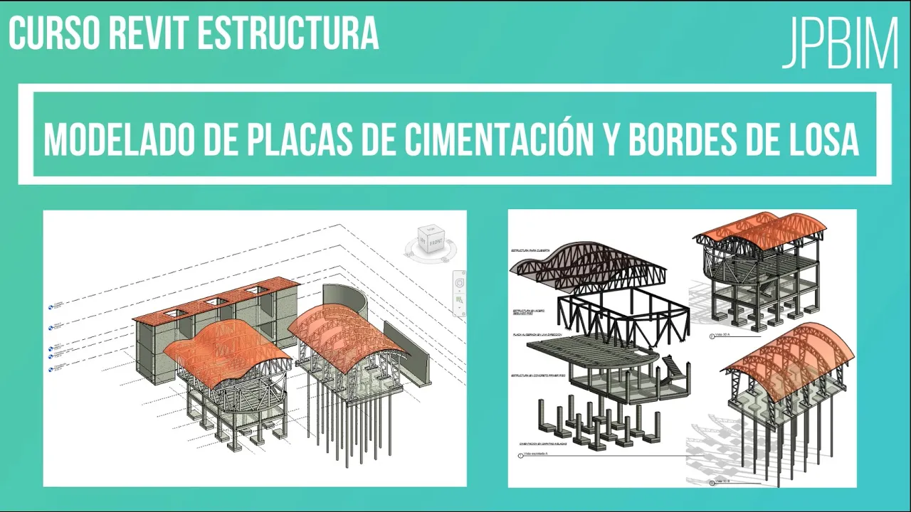
Video 6. Modelado de placas de cimentación (Cimentaciones parte 2) (CURSO REVIT ESTRUCTURA AVANZADO)
How to Create Foundation Slabs in Construction
Introduction to Foundation Slabs
- The video introduces the process of creating foundation slabs, specifically focusing on how to set up the slab's borders based on desired profiles.
Setting Up the Project
- The presenter emphasizes starting at Level 1 of the project plan, not at the foundation level which is below ground.
- To create a slab, users are instructed to navigate to the structure tab and select "slab," with an option for creating edges later.
Editing Slab Types
- The presenter demonstrates how to duplicate and edit slab types, naming it "foundation slab" with a thickness of 0.30 meters.
- Users can modify materials for each layer; in this case, concrete with a strength of 3,500 psi is chosen.
Drawing the Slab
- A rectangle is drawn using intersection points as references; adjustments are made by offsetting lines outward by 50 centimeters.
- The presenter explains moving selected lines using keyboard shortcuts for precise placement.
Finalizing the Foundation Slab
- Once completed, the foundation slab appears similar to standard slabs but is categorized as structural foundation in planning tables.
- Users can adjust elevation levels and offsets easily within their design software.
Creating Edges for the Slab
- The video transitions into adding edges around the created slab by selecting external lines and utilizing default edge types.
- Important tips include managing multiple edge types effectively without merging them unintentionally during modifications.
Modifying Edge Segments
- Instructions are provided on how to add or remove segments from edges while maintaining control over individual elements.
- Emphasis is placed on ensuring that changes can be made individually or collectively depending on user needs.
Creating and Modifying Profiles in Revit
Selecting Profile Types
- The speaker discusses editing profile types in Revit, highlighting the option to choose from predefined sizes such as 600x300 or 900x450.
- It is noted that while Revit defaults to three profile types, users can modify these profiles for specific needs, particularly focusing on concrete rather than steel.
Modifying Existing Profiles
- To modify a profile, the speaker instructs to navigate to the "families" section and search for "profiles" (or "perfiles" in Spanish).
- A demonstration of duplicating an existing profile type (900x450) is provided, with adjustments made to dimensions like thickness and width.
Creating New Profiles
- The process of creating a new profile involves selecting "File," then "New," followed by choosing family templates relevant to the project.
- The speaker emphasizes following a specific directory path within the computer's file system to access necessary templates for metric profiles.
Sketching Profile Shapes
- Users are guided on how to create sketch lines for their custom profiles, stressing the importance of defining dimensions accurately.
- Before drawing, it’s recommended to adjust unit settings from millimeters to meters for better accuracy during design.
Saving and Loading Custom Families
- After creating a custom profile shape, users are instructed on saving their work under a chosen name (e.g., “borde de losa tipo 1”).
- Instructions are given on loading this newly created family into an existing project model and ensuring it appears correctly in 3D views.
Editing Loaded Profiles
- Once loaded into the project, users can edit their custom profiles by duplicating them and adjusting material properties as needed.
- The speaker explains how modifications can be made directly within the project environment without affecting other instances of similar profiles.
Understanding Element Modification in Design Tools
Modifying Elements with Tools
- The discussion emphasizes the importance of modifying elements correctly when using design tools. It suggests that users should be cautious about how they add elements, particularly when dealing with multiple modifications at once.
- Users are advised to add one element at a time and use the escape function to manage additional elements effectively, especially when positioning them differently (e.g., outward vs. inward).
Creating Order in Design
- A practical example is provided where an order of elements is created by selecting a specific point as the upper reference. This allows for precise placement of new elements above or below existing ones.
- The speaker illustrates how selecting points can influence the hierarchy and arrangement of design components, enhancing overall organization.
Importance of Profiles in Architectural Design
- The speaker mentions a video resource related to profiles used in architectural designs, particularly for railings and stairs, indicating their frequent application in various families within design software.