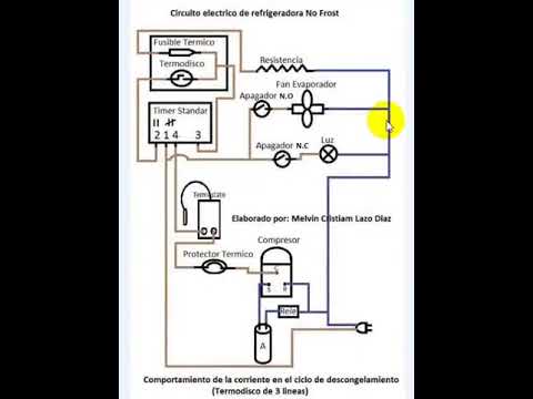
Circuito electrico de refrigerador no frost con termo disco de 3 lineas
Introduction to Refrigerator Diagrams
In this section, the speaker introduces the topic of refrigerator diagrams and mentions that they will cover different types of diagrams and their electrical functioning.
Types of Refrigerator Diagrams
- No frost refrigerators have a different electrical diagram compared to other types.
- These diagrams include a combined thermal fuse and thermostat component.
Electrical Components in Diagrams
The speaker explains the components found in refrigerator diagrams, focusing on the thermal fuse and thermostat.
Thermal Fuse and Thermostat
- No frost refrigerators use a specific type of thermal fuse called a "termo disco."
- The termo disco is combined with a thermal fuse in one package.
- The electrical diagram for refrigerators with this type of termo disco is different.
Understanding the Electrical Diagram
The speaker provides an explanation of how the electrical diagram functions.
Functioning of the Electrical Diagram
- The neutral line connects directly to the compressor, light, fan, and resistance without any interruption.
- In contrast, the live line may be interrupted by components such as timers or thermostats.
- During defrost cycles, the live line reaches the timer before continuing to other components.
Interruption in Live Line
The speaker discusses how the live line can be interrupted by certain components.
Interruption in Live Line
- The live line may be interrupted by components like timers or thermostats.
- In defrost cycles, the live line reaches the timer first before proceeding further.
Current Behavior during Defrost Cycle
The speaker explains the behavior of current during the defrost cycle with a three-line termo disco.
Current Behavior in Defrost Cycle
- During defrost cycles, the current enters the timer and then passes through to terminal 4.
- From there, it goes to the thermostat, which controls the compressor.
- This is a general overview of how the compressor is controlled during defrost cycles.
System Behavior during Defrost Cycle
The speaker describes the system behavior during defrost cycles and highlights specific components.
System Behavior during Defrost Cycle
- In defrost cycles, when observing the diagram, we can see that the live line feeds both the spark plug (bujía) and fan separately.
- The opening and closing of the refrigerator door control whether the light turns on or off and whether the fan operates.
- The main focus is on a specific point in this diagram where current enters terminal 1 of the timer.
Current Flow through Termo Disco
The speaker explains how current flows through the termo disco component during defrost cycles.
Current Flow through Termo Disco
- During defrost cycles, current enters terminal 1 of the timer and exits from terminal 2.
- It then travels towards the termo disco, passing through it.
- As we are currently in a defrost cycle with ice blocking airflow (eba),the termo disco remains closed.
Timer Functionality
The speaker discusses how timers function in relation to other components in refrigerators.
Timer Functionality
- In this system, terminals 1 and 3 of the timer are fed by live line simultaneously.
- Since both ends receive live line, the timer does not move and stops functioning.
- Technicians may mistakenly assume a faulty timer when it fails to advance during defrost cycles.
Understanding Timer and Termo Disco Interaction
The speaker explains the interaction between the timer and termo disco in this system.
Timer and Termo Disco Interaction
- The behavior of the termo disco is crucial in this system.
- During defrost cycles, when the termo disco is closed due to ice blockage, the resistance initiates defrosting.
- Once the coil is free of ice, the termo disco opens, allowing current to pass through it.
- This current then flows through the thermal fuse and reaches the resistance.
Current Flow after Defrost Cycle
The speaker describes how current flows after completing a defrost cycle.
Current Flow after Defrost Cycle
- After completing defrost cycles, current passes through the resistance as it behaves like a piece of wire at that moment.
- From there, it travels through another cable towards the thermal fuse but encounters an open termo disco.
- However, since the resistance has completed its defrosting function, energy manages to pass through this path.
Timer Functionality during Normal Operation
The speaker explains how timers function during normal operation after completing a defrost cycle.
Timer Functionality during Normal Operation
- During normal operation, when there is no ice blockage or defrost cycle occurring, current enters terminal 1 of the timer from live line.
- This causes terminal 3 to be energized as well. As both ends receive live line simultaneously, there is no movement in the timer.
- This behavior allows for continuous functioning without interruption.
Timer Functionality during Compressor Operation
The speaker discusses the functionality of timers during compressor operation.
Timer Functionality during Compressor Operation
- Current passes through the resistance, cable, thermal fuse, and enters the timer at terminals 3 and 1.
- As we already have live line in terminal 1, there is no change in behavior.
- The timer continues to function normally and initiates a cycle change by connecting terminal 1 to terminal 4.
- This allows current to flow directly to the thermostat and compressor, resulting in compressor activation.
Understanding Timer Behavior during Cycle Change
The speaker explains how timers behave during a cycle change.
Timer Behavior during Cycle Change
- During a cycle change, when the timer connects terminal 1 to terminal 4, it does not cause a short circuit.
- Instead, the resistance turns on because there is an accessory consuming energy in that section.
- When the accessory is off, it allows current to pass through without causing any issues.
Timestamps are approximate and may vary slightly.
Understanding the Flow of Energy
In this section, the speaker explains how energy flows through different components and what happens if certain elements are not functioning properly.
Energy Flow and Functionality
- The energy must pass through the resistance, travel through the cable, pass through the fuse, and reach terminal 3 of the timer.
- If the thermal fuse is open, preventing energy from reaching terminal 3, then it will not function properly.
Timestamps have been used to associate key points with specific parts of the video.