Funcionamiento básico del condensador
Introduction to Capacitors
In this lesson on analog electronics, the instructor introduces the concept of capacitors and their basic functionality. Capacitors are devices that can store a small amount of charge, measured in farads (F). The capacity of a capacitor determines the amount of charge it can store.
Types of Capacitors
- There are different types of capacitors, such as ceramic capacitors and electrolytic capacitors.
- Ceramic capacitors are commonly used in electronics and have smaller capacities.
- Electrolytic capacitors have larger capacities and are similar to the one being used in the demonstration.
Charging and Discharging
- When a capacitor is being charged, current flows through the circuit until it reaches its maximum capacity.
- Once fully charged, a capacitor does not allow any more current to pass through.
- A discharge circuit can be used to release the stored energy from a capacitor.
Time Constants
- The time it takes for a capacitor to charge or discharge depends on its capacity and the resistance in the circuit.
- The formula for calculating time constants is T = 5RC, where T is time in seconds, R is resistance in ohms, and C is capacitance in farads.
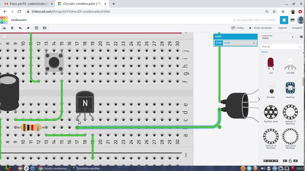
Circuit Demonstration
The instructor demonstrates a simple circuit using a resistor, LED, push button switch, and an electrolytic capacitor to visualize charging and discharging.
Circuit Setup
- Connect the negative terminal of the electrolytic capacitor directly to ground (negative).
- Connect the positive terminal of the electrolytic capacitor through a resistor to visualize charging.
- Connect an LED parallel to the resistor to observe current flow.
- Use a push button switch between positive voltage supply and connect it with other components.
Charging Process
- Pressing the push button switch allows current to flow through the circuit, charging the capacitor.
- The LED gradually brightens as the voltage across the capacitor increases.
Discharging Process
- Releasing the push button switch stops current flow and initiates discharging of the capacitor.
- The LED gradually dims as the voltage across the capacitor decreases.
Discharge Circuit Demonstration
The instructor demonstrates a discharge circuit using a resistor and an LED to observe how a charged capacitor discharges.
Discharge Circuit Setup
- Connect another push button switch in parallel with a resistor to create a discharge circuit.
- Connect the negative terminal of the LED to ground (negative).
- Connect the positive terminal of the LED to positive voltage supply through a resistor.
Discharging Process
- Pressing the second push button switch allows current to flow through the discharge circuit, causing the charged capacitor to discharge.
- The LED connected in parallel with the resistor gradually turns off as voltage across it decreases.
TinkerCAD simulation may not accurately represent real-world component behavior, but it provides an idea of how capacitors function in circuits.
Conclusion
In this lesson on analog electronics, we learned about capacitors and their basic functionality. We explored different types of capacitors, discussed charging and discharging processes, and observed demonstrations using simple circuits. Capacitors store charge and can be used in various electronic applications for energy storage and signal filtering purposes.
Charging and Discharging Capacitors
In this section, the speaker discusses how capacitors can be used to store and release charge. They explain that small charging and discharging currents allow capacitors to be used for timing processes.
Modifying a Circuit with a Transistor
- A circuit is modified by adding a transistor to control a device with higher power consumption.
- The capacitor is charged directly and discharged through a resistor instead of an LED.
- The base of the transistor controls the discharge, while the emitter is connected to negative and the collector can be connected to a high-power device like a lamp or bulb.
Applications of Capacitor Timing
- Capacitor timing can be used to delay the disconnection of a device, allowing an instant signal to have a prolonged effect.
- It can also stabilize an unstable signal by using the capacitor's stored charge during voltage fluctuations.
Using Relays for Higher Power Consumption
This section explores using relays instead of transistors for devices with even higher power consumption. The speaker demonstrates how relays can be employed in circuits for timing purposes.
Connecting a Lamp via Relay Contacts
- A lamp is connected through one of the relay's contacts.
- The positive terminal is connected to one terminal of the relay coil, while the other terminal is connected to the collector.
- Once activated, the relay changes its contacts, allowing current flow from common (COM) to normally open (NO) or normally closed (NC).
Timing Effect with Relays
- By pulsing the circuit, the lamp remains constantly lit due to capacitor stabilization.
- The duration of illumination depends on factors such as capacitor capacity and resistance value.
Conclusion
Capacitors can be utilized in circuits for timing purposes by controlling their charging and discharging processes. Transistors and relays can be employed to govern devices with higher power consumption, allowing for delayed disconnection and prolonged effects.
Understanding the Basic Circuit Operation
In this section, the speaker explains the basic circuit operation involving the charging and discharging of a capacitor, the use of a transistor to control current flow, and powering a relay coil.
Basic Circuit Operation
- The circuit consists of a capacitor that is charged and discharged through the base of a transistor.
- The discharge of the capacitor through the transistor's base controls the current flow.
- The transistor is used to power a relay coil.
Timestamps are not available for bullet points in this section.