Current Transformers (CT)
Current transformers are used extensively in metering and circuit protection. Eaton's Power Systems Experience Center is the ideal place to learn how to properly apply CTs considering accuracy, types, safety, temporary and permanent applications.
Current Transformers (CT)
Requesting a CT from the work room
The conversation starts with a request for a CT (current transformer) from the work room.
Getting the right size CT
- The speaker asks for a big CT to monitor the main breaker current accurately.
- They mention that as long as it fits around the wires, any size will work.
Different types and uses of CTs
The discussion moves on to different types and uses of CTs.
Various aspects of CTs
- There are different ratings, classes, and high-frequency options for measuring transients.
- The speaker mentions that they have been working on new demos with CTs.
Definition and purpose of current transformers
The speaker provides an explanation of what a current transformer (CT) is and its purpose.
Definition of a CT
- A CT is a device used to safely reproduce a low-level current that accurately represents a higher current level for metering and protection purposes.
- It is a current measuring device.
Calculation and measurement of current using CTs
The speaker explains how current can be calculated and measured using current transformers (CT).
Using Maxwell's equations
- By applying Maxwell's equations, specifically Ampere's Law, it is possible to calculate and measure current using CTs.
- Magnetic field integration around a closed loop of wire yields the net enclosed current value.
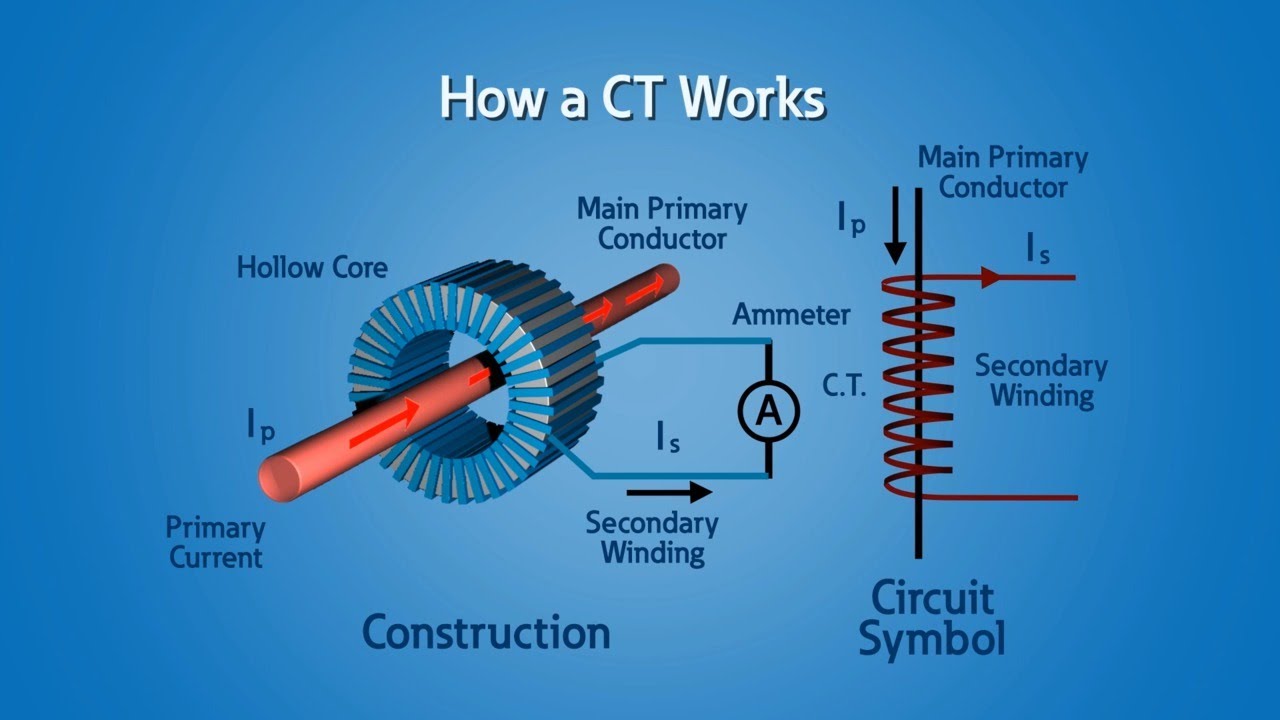
Structure and operation of CTs
This section focuses on the structure and operation of current transformers (CT).
Closed-loop instruments
- CTs consist of a magnetic core with a secondary winding around it.
- The primary winding carries the current to be measured, while the secondary winding produces an output proportional to the current flowing through the core.
Secondary winding and ratings of CTs
The speaker explains the relationship between the primary and secondary windings of CTs and their ratings.
Proportional current on the secondary winding
- The current on the secondary winding is directly proportional to the current flowing through the center of the core.
- Typical secondary ratings are 5 amps or 1 amp, with different turns ratios.
Types and applications of CTs
This section discusses different types and applications of current transformers (CT).
Solid core, split core, and clamp-on CTs
- CTs can be solid core, split core, or clamp-on styles.
- Solid core CTs are more permanent and commonly used for metering and protection in switchboards, panel boards, and switchgear.
- Split core and clamp-on CTs are used in temporary applications such as power quality instrumentation.
Monitoring current with CTs
The speaker explains how CTs are used to monitor current in various applications.
Monitoring power usage
- Utilities use CTs at customer's incoming service to monitor current and power usage for billing purposes.
- Permanent CT installations can be found in generators, transformers, connected loads, or anywhere there is a need to monitor current flow.
Protection applications of CT
This section focuses on using CT for protection purposes.
Trip units for circuit breakers
- In combination with trip units for low voltage circuit breakers or relays for medium voltage breakers, CT can help trip the breaker during overloads or faults.
- Many circuit breakers have built-in CTs for current monitoring.
Ground fault protection with CT
The speaker explains the use of special CTs for ground fault protection.
Detecting ground faults
- Ground fault protection uses a special type of CT where all phases and neutral conductors pass through it.
- If there is any residual current (current coming in on one phase but not returning on others), it indicates a ground fault.
Importance of accurate CT measurements
This section emphasizes the need for accurate current measurements with CTs.
Revenue-grade accuracy
- CTs used for billing purposes must be extremely accurate and are considered revenue grade.
- Permanent CT installations also monitor power and power factor to optimize real and reactive power.
Different types of CT sensors
The speaker clarifies the terminology around different types of CT sensors.
Functionality remains the same
- Some people refer to mounted CTs inside switchgear or circuit breakers as sensors, but their functionality and purpose remain the same: to provide current measurements at a useful level.
Special considerations for ground fault protection
This section discusses specific considerations when using CT for ground fault protection.
Ground fault detection
- For ground fault protection, a separate type of CT is used to detect residual currents that indicate a ground fault.
- The level at which a ground fault is triggered varies depending on the application (e.g., 5 milliamps in homes, higher levels in industrial plants).
Insulation requirements for medium voltage applications
The speaker addresses misconceptions about insulation requirements for medium voltage applications involving CT.
Insulation rating
- Contrary to common belief, the insulation of CTs does not need to be rated for the line voltage they measure.
- CTs are installed around already insulated and typically shielded conductors.
Accuracy and ratings for protection applications
This section emphasizes the importance of accurate current measurement ratings for protection applications.
Accurate measurement during fault conditions
- CTs used in protection applications must be rated to accurately measure high currents that occur during fault conditions (usually 20 times full load amps).
- This ensures proper breaker tripping without saturation and incorrect results.
Different ratios and selection options for CT
The speaker explains the different ratios and selection options available for current transformers (CT).
Ratio example
- A 300:5 amp CT means that a wire carrying 300 amps AC through the core will produce 5 amps on the secondary winding.
- Most CTs have a 5 amp output, but some have a 1 amp output.
Interfacing with meters or circuit breakers
This section discusses how to interface CT with meters or circuit breakers.
Correct multiplier
- When interfacing with a meter or circuit breaker, it is important to use the correct multiplier to convert the 5 amp or 1 amp output to the actual measured value.
- The voltage on the secondary winding increases compared to the primary winding.
Safety precautions when using CT
The speaker highlights safety precautions when using current transformers (CT).
Shorting of secondary winding
- To ensure safety, it is recommended to short-circuit the secondary winding of CT when not in use.
- This can be done using a shorting block or temporary jumper.
Current output and terminating resistor
This section explains the current output and use of terminating resistors in temporary CTs.
Output for metering
- All CTs output a current that is used for metering.
- Temporary CTs, such as those used in power quality instruments
New Section
This section discusses the accuracy and methods of increasing current flow through a CT (Current Transformer) for more accurate measurements.
Increasing Current Flow Through a CT
- A CT may not be accurate at less than 10% of its full load rating.
- To increase the amount of current flowing through the core, especially for temporary metering, looping the primary wire several times through the core can be done.
- For example, looping the wire five times through the core of a 500:5 amp CT will make the CT ratio 100:5 amps.
- By increasing the current flowing through the core, the measurement becomes more accurate.
New Section
This section explains accuracy classes and overload currents in CTs.
Accuracy Classes and Overload Currents
- CTs come in different accuracy classes. For example, a class one CT has a primary to secondary current error of 1% at rated current.
- A lower-rated CT, such as a 0.5 rated CT, has an error of 0.5% or less.
- Accuracy is crucial for protective relaying and metering purposes.
- Overload currents beyond normal ratings are required to ensure accurate performance during system faults.
New Section
This section discusses different ratings and VA capabilities of CTs.
Ratings and VA Capabilities
- A current transformer can have ratings ranging from C10 to C800.
- The rating is related to the secondary winding output voltage capabilities and VA rating of the CT.
- Higher-rated CTs can sustain more burden on their secondary without saturating.
- For example, a C400 current transformer can handle a maximum burden that would drive up to 400 volts.
New Section
This section explains the excitation performance and saturation curves of CTs.
Excitation Performance and Saturation Curves
- Manufacturers provide graphs of the excitation performance of a CT.
- These graphs help determine the CT's performance over the entire range of secondary current.
- The graph ensures that the CT will function as required and not saturate.
- Special testers can be used to verify CT ratio and saturation curves.
New Section
This section discusses the linearity, knee point voltage, and frequency range of CTs.
Linearity, Knee Point Voltage, and Frequency Range
- CTs are generally linear within 10% to 90% of their ratings but may change significantly outside that range.
- The knee point voltage is the magnitude at which the output current no longer linearly follows the input current. It indicates saturation.
- During faults, protection CTs can experience 20 to 30 times rated current.
- The maximum frequency range for most CTs is typically three to five kilohertz.
New Section
This section explains highly accurate CTs for high-frequency applications.
Highly Accurate CTs for High-Frequency Applications
- For high-frequency applications like transients in the hundreds of kilohertz or megahertz range, special highly accurate CTs can be used.
- Pearson CTs are an example of such highly accurate CTs.
New Section
This section covers polarity markings and common issues with using CTs.
Polarity Markings and Common Issues
- Polarity dots, arrows, or markings indicate current flow direction in a CT.
- Primary wire enters from H1 or P1 side, while load side is indicated by H2 or P2.
- Negative power measurement can occur if the primary orientation or secondary wiring is incorrect.
- Phase shift between primary and secondary windings can lead to incorrect power measurements.
- CTs have volt ampere or capacity ratings and limits on the number of devices and length of wire connected to their secondary side, known as burden.
New Section
This section explains other methods of measuring current, including current shunts, hall effect sensors, and Rogowski coils.
Other Methods of Measuring Current
- Current shunts, hall effect sensors, and Rogowski coils are alternative ways to measure current.
- Current shunts use a known value sense resistor in combination with a differential voltmeter to measure current passing through the resistor.
- Hall effect sensors require an additional DC supply to produce a constant magnetic field for detecting current.
- Rogowski coils are used for measuring AC currents.
Conclusion
These notes provide an overview of various aspects related to CTs, including increasing current flow, accuracy classes, overload currents, ratings and VA capabilities, excitation performance and saturation curves, linearity and knee point voltage, frequency range limitations, highly accurate CTs for high-frequency applications, polarity markings and common issues with using CTs. Additionally, other methods of measuring current such as current shunts, hall effect sensors, and Rogowski coils were mentioned.
Different Ways to Measure
This section discusses the various methods of measurement and their applications.
Measurement Techniques
- There are different ways to measure, such as using amplification and a DC power supply like a hall effect sensor.
- Rogowski coils are used for current monitoring in precision welding systems, arc furnaces, and other electronic equipment where high frequency measurements are required.
Conclusion
- The speaker expresses surprise at the number of different ways to measure.
Timestamps have been associated with the corresponding bullet points based on the provided transcript.