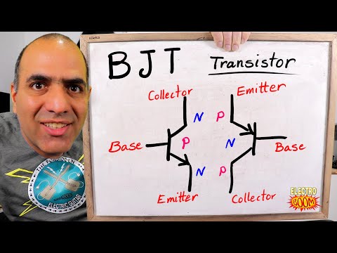
Starter Guide to BJT Transistors (ElectroBOOM101 - 011)
Introduction to Transistors
Overview of Transistors
- Transistors are likened to the "Michael Jackson" of electrical components, widely recognized yet often misunderstood.
- They are essentially variable resistors or adjustable potentiometers, but with non-linear resistance characteristics.
Types of Transistors
- The main types discussed are Bipolar Junction Transistor (BJT) and Metal-Oxide-Semiconductor Field-Effect Transistor (MOSFET), focusing primarily on BJT in this video.
Understanding BJT
What is a BJT?
- BJT stands for Bipolar Junction Transistor, made from silicon semiconductors similar to diodes.
- A BJT consists of two PN junctions, resembling two diodes in series but functioning differently.
Structure and Functionality
- The terminals of a BJT are named base, emitter, and collector; flipping the collector and emitter leads can lead to poor performance.
- When a positive voltage is applied across the collector-emitter terminals and current flows through the base-emitter junction, it allows a larger current to flow from collector to emitter.
Current Relationships in BJTs
Current Flow Dynamics
- The relationship between base current (Ib), collector current (Ic), and emitter current (Ie): Ic = β * Ib where β is the transistor's gain.
- Emitter current is approximately equal to collector current due to Ib being much smaller than Ic.
Active Region vs. Saturation Region
- The active region allows for stable operation where Ic remains relatively constant despite changes in Vce until saturation occurs.
PNP vs. NPN BJTs
Differences Between PNP and NPN
- PNP transistors operate similarly to NPN but with reversed voltages and currents; understanding both types is crucial for applications.
Building an Amplifier Circuit
Designing a Simple Amplifier
- A simplified Class A amplifier circuit demonstrates how BJTs amplify signals by increasing base current into beta times at the collector.
Biasing Techniques
- Proper biasing sets DC operating points for optimal AC signal amplification without distortion; choosing appropriate resistor values is essential.
Signal Distortion Considerations
Managing Input Signals
- Keeping input signals small ensures linearity in output; excessive input can distort signals as they approach saturation limits.
Conclusion & Learning Resources
Educational Recommendations
- The video concludes with a recommendation for Brilliant.org as an interactive learning platform that offers courses on math, science, and computing.